

61
Incident light interference contrast ICR
Adjust the microscope as for brightfield examina-
tions.
The Smith reflector (31) is an excellent alterna-
tive to the BF reflector for ICR due to the low
depolarisation at the beamsplitter plate
Insert the
incident light polariser L ICR/P
with
compensator, reversible (81, 78.2) and
analyser
IRM ICR/P
into the light path.
Deactivate the compensator in the polariser (turn
over by 180°, see
l
engraving)
Switch the ICR prism turret to the brightfield set-
ting (BF) so that the ICR prisms are out of the light
path (76.2, 81a.1).
Focus on a homogeneous, strongly reflecting
specimen.
Swing the analyser IRM ICR/P (76.3) round the
zero position until the greatest possible extinc-
tion is attained.
n.b.: The polariser and analyser must be exactly
crossed to obtain good ICR quality.
Instead of the polariser and analyser in the slide
and the BF or Smith reflector, the ICR reflector
module with built-in polariser and analyser and
the MgF
2
plate can be used (although colour
interference contrast is then only possible by
considerably altering the position of the ICR
prism turret (76.2)).
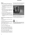
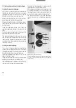
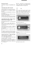
Swing in an ICR prism by rotating the prism turret
(76.2) and set ICR contrast on the prism turret
with the knurled knob (34.6, 76.6, 81.2). In addition,
adjust the aperture diaphragm to optimise image
contrast.
To set ICR colour contrast, turn the polariser
L ICR/P over by 180° so that the lambda engraving
points towards the user (the compensator is now
between the crossed polariser/analyser.)
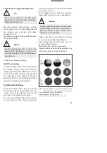
Choice of ICR prisms:
The right type of prism for the particular objective
is engraved on the objective sleeve.
e.g. Prism A for N PLAN 5x and 10 x objectives
Prism D, D1 for N PLAN 20 x, 50 x, 100 x and
PL FLUOTAR 5 x-100 x objectives
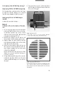
Prism D features greater shearing, providing high-
er detection sensitivity for minute topological
differences.
Instead, prism D1 can be used, which has less
shearing than prism D. Although it has lower
detection sensitivity for topological differences,
it offers better lateral resolution of structures.
The shearing effect is not as pronounced in all
directions.
For linear object structures, therefore, the speci-
men has to be rotated to obtain the most favoura-
ble contrast position.
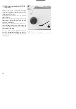
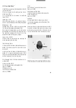
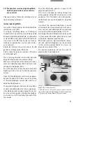
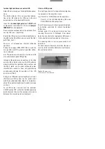
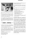
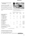
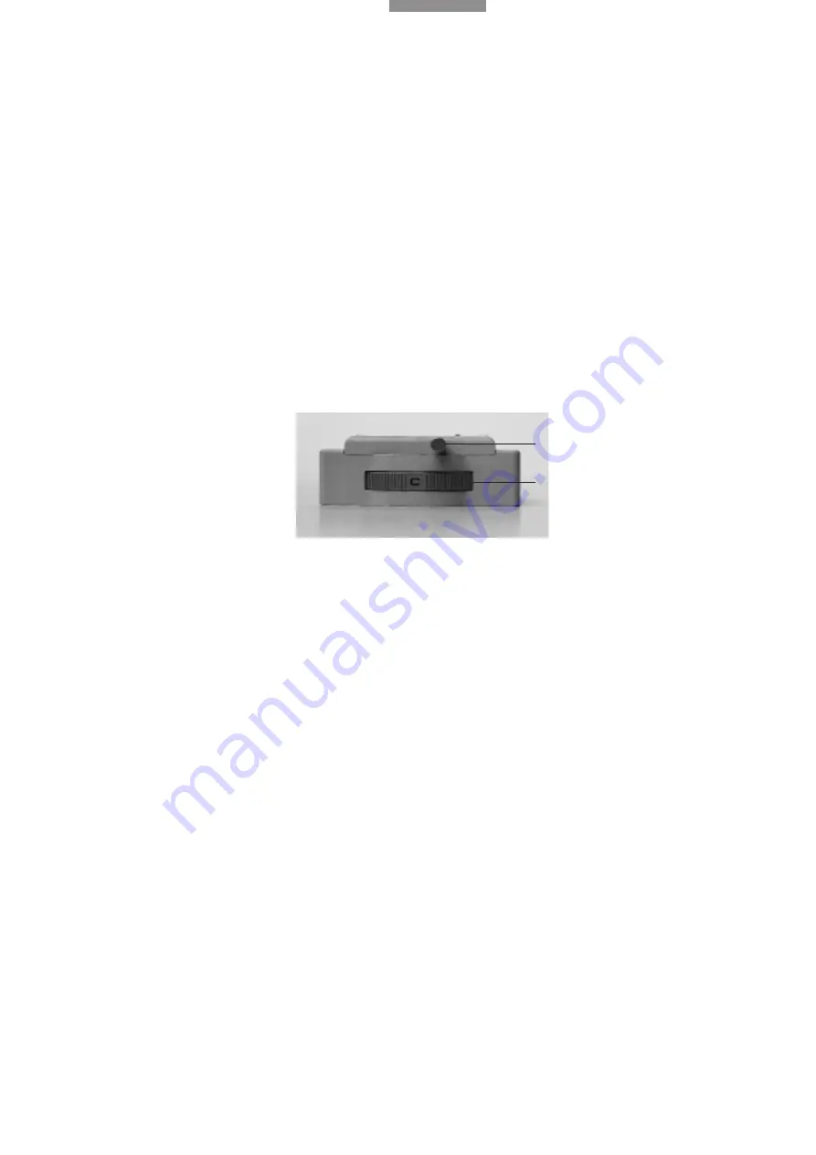
Fig. 81a
ICR prism turret
1
Prism turret,
2
Knurled knob
2
1