background image

iCONgrade, Operation

43

2.7

3D Sensors

How to set 3D sensor 
type

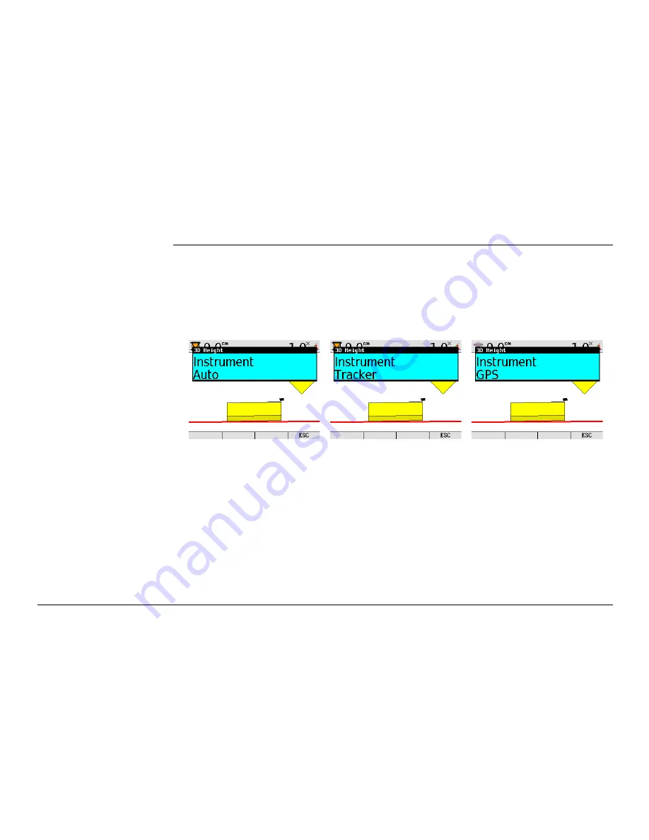
Select 3D Height (press the 

left or right (sensor) key

 once), and then press the 

Adjust


function key to enter the adjust menu. 

Note that it's only the current selected sensor in either left or right side that is 
adjusted.

If the 3D system is configured to indicate which sensor is currently in use, select 

AUTO

If not, then select either 

TRACKER

 or 

GPS

 from the menu.

Once 

Auto / GPS / Tracker

 is selected, it is required to 

EXIT

 from this menu for the change 

to take effect and then re-enter the menu to adjust gains.

Gains need to be set for both GPS or Tracker depending on which sensor is used. If AUTO is 
selected, the iCP32 will use the gains set in the Tracker and GPS settings.

Use the right arrow key to enter the gains settings.

Refer to chapter "2.8 Setting the Value for Gain and Deadband" for configuring Gains.

Summary of Contents for iCONgrade iCP32

Page 1: ...Leica iCONgrade iCP32 User Manual Version 1 0 English ...

Page 2: ...rough the User Manual before you switch on the product To ensure safety when using the system please also observe the directions and instructions contained in the User Manual and Safety Handbook issued by the Machine manufacturer Product identification The type and serial number of your products are indicated on the label on the base of the unit Enter the model and serial number in your manual and...

Page 3: ...ult in death or serious injury Warning Indicates a potentially hazardous situation or an unintended use which if not avoided could result in death or serious injury Caution Indicates a potentially hazardous situation or an unintended use which if not avoided may result in minor or moderate injury and or appreciable material financial and environmental damage Important paragraphs which must be adhe...

Page 4: ...ation circle center shift or wheel lean on Grader 19 2 1 4 Grader blade cushioning off 21 2 1 5 No blade rotation on Dozer 22 2 2 Select the Input Source 23 2 3 Setting a Reference Height 26 2 4 Using the MUS1300 Tri Sonic Sensor 28 2 4 1 Installation and Set Up Tri Sonic Sensor 32 2 4 2 Operation with the Tri Sonic Sensor 34 2 4 3 Swap Function 37 2 5 Using the Laser Sensor 39 2 6 SP14 Sensor 41 ...

Page 5: ... 4 Safety Directions 60 4 1 General 60 4 2 Intended Use 60 4 3 Limits of Use 61 4 4 Responsibilities 61 4 5 Hazards of Use 62 4 6 Electromagnetic Compatibility EMC 66 4 7 Labelling 68 5 Technical Data 74 5 1 iCP32 Technical Data 74 5 2 Conformity to National Regulations 81 6 International Limited Warranty Software License Agreement 82 ...

Page 6: ... LCD colour screen making it easy to use even in bright sunny conditions The rugged IP56 enclosure is designed for harsh environments Power supply commu nication The control panel is powered from a cradle based on a sophisticated induction solution while data is transferred wirelessly via infrared between the MMB1300 cradle and the iCP32 control panel The MMB1300 will be called the Cradle througho...

Page 7: ...his product may be installed on building machinery only by an appropriately trained and qualified specialist a Graphical display b Grade indication LEDs c Left Right side sensor setup d Speaker e Menu key f Function keys g Enter key iCP32_001 a b b c c d e f g ...

Page 8: ...r the function and safety of the machine Precautions Follow the instructions of the machine manufacturer If no appropriate instruction is avail able ask the machine manufacturer for instructions before mounting the product Keys Up key Down key Enter key Auto Manual key Menu key Sensor select key Fuction keys ...

Page 9: ...iCONgrade Product Overview 9 Display a Side shift alignment indication b Above grade c Left Right on grade indication d Below grade iCP32_002 a b b c c d d ...

Page 10: ...10 iCONgrade Product Overview MMB1300 Cradle a Power and data transfer LED indicators b Holding magnets c On off switch d Release key for control panel iCP32_003 a b c d ...

Page 11: ... started complete the following steps 1 Snap control panel onto cradle To connect the control panel to the cradle 1 Put the control panel on the holding hooks in the bottom of the cradle 2 Then snap the control panel onto the cradle by pressing it towards the cradle iCP32_004 1 1 2 ...

Page 12: ...switch on the right side of the cradle This is the master switch for the entire system Removing the panel will also turn off the power To release the control panel simply press the release key at the bottom of the cradle and pull the control panel towards you and then lift it up iCP32_005 iCP32_006 2 1 ...

Page 13: ... for that sensor The left and right hydraulic channel has four sensor setup keys each Auto Manual key up key down key sensor select key External Multi Switch for Grader The system can also be fitted with an External Multi Switch This switch has three keys on it One Auto Manual key Red and a set of up and down keys green These keys have the same function as the corresponding keys on the control pan...

Page 14: ...switch for Dozer Toggle the master switch to AUTO to enable automatic control on all chan nels selected on the control panel Toggling the master switch to MAN places all channels in manual control regardless of selection on the control panel ...

Page 15: ...iCONgrade Product Overview 15 ...

Page 16: ...ime the blade changes attack angle pitch 2 1 2 Mast orientation No articulation and circle side shift on Grader Every time a job is to be made with a single eleva tion sensor cross slope sensor on a Grader 2 1 3 No Articulation circle center shift or wheel lean on Grader Turn Grader blade cushioning off Every time you want to use automatic controls on a Grader 2 1 4 Grader blade cush ioning off Do...

Page 17: ...rader system Ensure that mast is perpendicular to the wheelbase or use a mast slope sensor Keep the circle centered under the gooseneck Do not lean the wheels Do not articulate the machine Where possible move the machine in one direction only do not turn around Where possible set the blade rotation and leave it in the same position Where possible run with the slope sensor trailing not leading ...

Page 18: ...asured position that is the position the mast or masts were in during the mast measure up On a Dozer this means that the mast should not be mechanically sloped If for some reason the mast is actually mechanically sloped a new mast measure up must be done On a Grader the blade should be tipped back towards its end stop if that was the original measure position ...

Page 19: ...ulation circle Centershift and wheel lean For Grader systems that rely on the cross slope sensor and a single elevation sensor you must make sure that the machine is not articulated and that there is no side shift applied to the circle The front wheels must be upright not leaned Okay Articulated ...

Page 20: ...n the reading from the mainfall sensor Articulation and circle Centershift introduce unmeasured blade rotation Operating with wheel lean circle centershift or articulation can cause inaccuracy in the cross slope being cut Circle center shifted Wheel leaned ...

Page 21: ...ning off Using a Grader s blade cushioning device at the same time as the blade is being automatically controlled by the system results in poor automatic control performance Make sure that blade cushioning if installed is turned off before working with automatic controls ...

Page 22: ...is square to the machine not rotated Operating with a rotated blade can cause inaccuracy in the cross slope being cut When driving on a surface that has 0 cross slope and 0 long slope the blade can be rotated freely The bigger cross slope and long slope you are working with the bigger the error on a rotated blade will be Dozer blade square Dozer blade rotated ...

Page 23: ...iCONgrade Operation 23 2 2 Select the Input Source Sensor selection 1 Push the left or right key to open the sensor selection menu Following screen appears ...

Page 24: ... through the available sensors a If the sensor is connected and active it will show up in black b If it s not connected or inactive it will show in red 3 Highlight the sensor that is going to be used and exit the sensor selection menu by pressing or ...

Page 25: ...all icon in the upper corner of the display and by an icon shown on the blade in relation to the actual placement of the sensor Example a Laser indication b Cross Slope A cross slope is selected in the right side and in the left side a Laser Sensor is selected a b ...

Page 26: ...de In seek mode the screen shows the current sensor value of the selected sensor Pressing both keys simultaneously again exits the seek mode Or press or for seek mode While in Seek Mode the height values at the top of the screen will be green If both keys are pressed and held for more than three seconds the control panel will take the current sensor value and store as the new reference height Whil...

Page 27: ... the operator can select in which direction the mast should start moving to look for the laser beam using the and keys The mast will then start moving in that direction until the laser sensor has the beam centered If the mast during a seek reaches its top or bottom limit it will automatically switch moving direction and continue to seek for the laser beam until it is found or it hits the next end ...

Page 28: ... 1 Place the machine so that the Tri Sonic is above ground the edge or stringline The sensor needs an edge or string to follow before it can control the sideshift 2 Move the blade to the working position 3 Move the Tri Sonic to a good working height This is approximately 60 cm above the reference 4 Select the Tri Sonic on the same side as where it is placed on the machine 5 Enter the Tri Sonic men...

Page 29: ... between the different modes Ground Mode Edge Mode Stringline Press the or key to toggle between the modes Once selected press the key Following screens will appear by pressing the up or down Enter key to toggle between the screens ...

Page 30: ... Edge and Stringline modes 6 Go to the Sideshift menu option and set it to Yes 7 Press both and keys simultaneously to set the control panel in seek mode 8 Check that the height is approximately 60 cm 9 Press both and keys simultaneously or press seek function key and keep them pressed for three seconds to set the reference height 10 Press the right key to set the machine in Auto Mode ...

Page 31: ...iCONgrade Operation 31 11 Press the Side A M function key to enable the automatic sideshift control ...

Page 32: ...cording to the machine and reference In case of large differences in temperature between the storage and working environments allow 30 minutes for the sensor to adapt to the working environment prior to operation The direction of move ment of the Tri Sonic sensor While ground and curb scanning the Tri Sonic should move longitudinally for the averaging of the scanned values For Stringline and Edge ...

Page 33: ...Mounting the Tri Sonic on the support Normal operation Edge operation 1 Release the clamping screw on the support 2 Insert the round centering pivot on the top of the sensor housing vertically into the support 3 Rotate the sensor to the required sensing mode refer to previous page 4 Lock the centering pivot of the sensor with the clamping screw For sensing Edges it is required to tilt the sensor t...

Page 34: ...ask iCP32 system can be operated in various combinations for the most demanding job requirements Mount the Tri Sonic Mount the Tri Sonic to the appropriate height for its maximum performance according to the reference used The sensing range shows the mimimum and maximum values possible wherever it can be achieved to obtain the range of best perfomance Sensing range Reference Sensing Range Best Per...

Page 35: ...iCONgrade Operation 35 Reference ground Reference stringline a Side View b Ground 90 a b a Side View b String 90 a b ...

Page 36: ...nd use the flat surface of the gutter as the reference as shown here Setup over an EDGE Use of the curb edge as a reference requires extra care be taken to ensure a proper distance and control of iCP32 system Unlike a string or a flat surface a curb edge can present some special problems It is best that this mode be used only by experienced operators Over any reference It is important to rotate an...

Page 37: ...ctual target slope will be inversed The SWAP function can also be activated by pressing the up key on both external multi switches simultaneously Level 2 Requirements Two Tri Sonic sensors must be connected and the system must be in Grader mode 1 Move the Grader to a flat level ground 2 Set the moldboard level with the machine 3 Select slope on left side and sonic on right side Choose ground mode ...

Page 38: ...38 iCONgrade Operation It is possible to have different heights and mode settings for the two Tri Sonic sensors ...

Page 39: ... Select the Laser Sensor on one of the sides 2 Place the cutting edge of the blade at the desired height 3 Move the mast up or down until the Laser Sensor detects the laser beam Continue to move the mast until the indication led s on the Laser Sensor is showing a green line 4 Press the left key to set the machine in Auto Mode 5 When the control panel is in Auto Mode the machine will start to move ...

Page 40: ...e cutting edge of the blade at the wanted height 3 Enter SEEK mode 4 Press the or key to tell the mast in which direction it should start to seek The mast will now move in the given direction until the Laser Sensor detects the laser beam and has it in the center of the sensor 5 Press the left key to set the machine in Auto Mode 6 The and keys can now be used to move the mast up or down and thereby...

Page 41: ...d speed compared to a system without SP technology The SP Technology can only be used on Dozers with the Control Box iCP42 together with PowerBox or PowerTracker The SP Technology MUST be turned off when using the SP14 sensor together with a laser or sonic sensor Enabling the SP14 Sensor If the system is equipped with a SP sensor it is recommended to have it enabled at all times SP functionality c...

Page 42: ... in greater smoothness increased operation speed and a system that is more robust against poor GPS coverage For a system with PowerTracker SP technology results in greater smoothness increased operation speed and a system that is more robust against losing the prism in case of the beam being interrupted ...

Page 43: ...or is currently in use select AUTO If not then select either TRACKER or GPS from the menu Once Auto GPS Tracker is selected it is required to EXIT from this menu for the change to take effect and then re enter the menu to adjust gains Gains need to be set for both GPS or Tracker depending on which sensor is used If AUTO is selected the iCP32 will use the gains set in the Tracker and GPS settings U...

Page 44: ... sensor key once and then press the Adjust function key to enter the adjust menu Note that it s only the current selected sensor in either left or right side that is adjusted Set gains for 3D Slope as explained in chapter 2 8 Setting the Value for Gain and Dead band ...

Page 45: ...e or key to scroll through the settings 3 Use the or key to change the value 4 To exit the adjust menu press the menu key Deadband The deadband controls the precise motion of machine hydraulics These values do not corre spond to accuracy but only to hydraulic speeds These values should not be confused with overall machine performance and or precision The automatic hydraulic calibration will set th...

Page 46: ...ded not to change these values Elevation Press the Test button to adjust the value so that it corresponds to the below distances For example during 2 seconds of movement the blade should move 13 cm for GPS Second laser for cross slope This should be measured 1 5 meters from the centre of the blade Press the Test button to adjust the value so that it corresponds to the below distances For example d...

Page 47: ...it corresponds to the below distances For example during 2 seconds of movement the blade should move 8 cm for 3D cross slope on Dozer Sideshift Grader only Enter the Tri Sonic or 3D height adjust menu Press the Test button to adjust the value so that it corresponds to the below distances 2D and 3D sideshift 13 cm Sensor Dozer Grader 2D and 3D cross slope 8 cm 14 cm ...

Page 48: ...also be done when changing the blade wear edges or changing tires on a grader as this will change the mainfall slope This is done by entering the calibration wizard Menu Calibration Sensor Calibration and following the on screen instructions Sensor Calibration 1 step Select the Sensor Calibration Follow the on screen instructions to calibrate each sensor The following example is for graders but th...

Page 49: ...ear Sensor Calibration 2 step Park the machine on a flat hard and level surface preferably a paved road or similar This will facilitate turning the machine around and proper machine alignment If the machine is already aligned properly and is ready for calibration skip ahead by pressing Skip F2 To start select Next ...

Page 50: ...ront wheels and articulation This ensures correct values for calibrating the mainfall sensor Select Next when complete Sensor Calibration 4 step Centre the machine link bar It must then be set in its centred position for proper Cross Slope calibration Select Next when complete ...

Page 51: ...s is important for the measurements in the next step Select Next when complete Sensor Calibration 6 step Rotate the blade so that the distance from the swivel to each blade tip is the same This ensures that the blade is perfectly perpendicular to the axis along the machine This is important for the correct calibration of the rotation sensor Select Next when complete ...

Page 52: ...e blade gently on solid blocks or other solid reference ensure the blade has not rotated or sideshift has been altered Select Next when complete Sensor Calibration 8 step The rotation sensor will automatically calibrate while at the same time collecting Mainfall and Cross Slope data Select Next when complete ...

Page 53: ...that the blade is not rotated or sideshift has altered Align the wheels using the markings from the previous step This is important for the correct measure ment of the Mainfall and Cross Slope values Select Next when complete Sensor Calibration 10 step The Mainfall and Cross Slope sensors will now be automatically calibrated Select Next when complete ...

Page 54: ...54 iCONgrade Operation Sensor Calibration 11 step The calibration routine is complete Save the calibrated values and exit the wizard by pressing Save To exiting the wizard without saving press Exit ...

Page 55: ...trol panel b MMB1300 Cradle c External Multi Switch d Cross slope sensor e Rotation sensor f Laser receiver g MPM700 Electric Mast manual mast h Sonic Tracker i MJB1301 Junction box Grader j Hydraulic valve k Machine battery MLS700 MLS700 a b c c d e f f g g h h i j k ...

Page 56: ...Cradle c External Switch for Dozer d Laser receiver e MPM700 Electric Mast manual mast f MJB1300 Junction box Dozer g Machine battery h Hydraulic valve i Cross slope sensor or SP14 Sensor j Remote junction box k Remote display MLS700 MLS700 a b c d d e e f g h i j k k ...

Page 57: ...iCONgrade Operation 57 ...

Page 58: ...d always make sure that you carry the product in its original transport container Transport in a road vehicle Never carry the product loose in a road vehicle as it can be affected by shock and vibration Always carry the product in its transport container and secure it Shipping When transporting the product by rail air or sea always use the complete original Leica Geosystems packaging transport con...

Page 59: ...the cloth with water or pure alcohol Do not use other liquids these may attack the polymer components Cables and Plugs Keep plugs clean and dry Blow away any dirt lodged in the plugs of the connecting cables Damp products Dry the products at a temperature not greater than 40 C 108 F and clean them Do not repack until everything is completely dry ...

Page 60: ...e distance between the blade bucket and a reference model surface line or point Automatic adjustment of a dozer grader hydraulic system in order to match the blade to the reference model Adverse use Use of the product without instruction Use outside of the intended limits Disabling safety systems Removal of hazard notices Opening the product using tools for example screwdriver unless this is speci...

Page 61: ...nd safety of the machine Precautions Follow the instructions of the machine manufacturer If no appropriate instruction is avail able ask machine manufacturer for instructions before mounting or installing the product 4 3 Limits of Use Environment Suitable for use in an atmosphere appropriate for permanent human habitation not suitable for use in aggressive or explosive environments Danger Local sa...

Page 62: ...osystems immediately if the product and the application becomes unsafe Warning The person responsible for the product must ensure that it is used in accordance with the instructions This person is also accountable for the training and the deployment of personnel who use the product and for the safety of the equipment in use Warning Unauthorized modification of machines by mounting the product may ...

Page 63: ... and after important meas uring tasks Warning While steering or navigating the machine accidents may occur due to a the operator not paying attention to the surroundings persons ditches traffic etc or b malfunctions of a system component interference etc Precautions The operator assures that the machine is operated guided and monitored by a qualified user e g driver The user has to be able to take...

Page 64: ...a safe distance from electrical installations If it is essential to work in this environ ment first contact the safety authorities responsible for the electrical installations and follow their instructions Warning During dynamic applications there is a danger of accidents occurring if the user does not pay attention to the environmental conditions around for example obstacles excavations or traffi...

Page 65: ...sonous gas are produced which may impair health If batteries are damaged or are heated strongly they can explode and cause poisoning burning corrosion or environmental contamination By disposing of the product irresponsibly you may enable unauthorized persons to use it in contravention of the regulations exposing themselves and third parties to the risk of severe injury and rendering the environme...

Page 66: ...rce in this respect Leica Geosystems cannot completely exclude the possibility that other equipment may be disturbed Caution There is a risk that disturbances may be caused in other equipment if the product is used in conjunction with accessories from other manufacturers for example field computers personal computers two way radios non standard cables or external batteries Precautions Use only the...

Page 67: ...mple near radio transmitters two way radios or diesel generators Precautions Check the plausibility of results obtained under these conditions Warning If the product is operated with connecting cables attached at only one of their two ends for example external supply cables interface cables the permitted level of electromagnetic radiation may be exceeded and the correct functioning of other produc...

Page 68: ...iCP32 Grading 2D Panel P N 798669 797050 S N xxxxxxxx xxxxxxxx Leica Geosystems AG CH 9435 Heerbrugg Made in Denmark 20XX Power 12 24 V DC 6A max iCP32_007 TYPE MMB1300 P N 764910 764910 S N XXXXXXXX 131441XX Leica Geosystems AG CH 9435 Heerbrugg Made in Denmark 20XX Power 12 24 V DC 6A max iCP41_009 ...

Page 69: ...x Leica Geosystems AG CH 9435 Heerbrugg Made in Denmark 20XX Power 12 24 V DC 6A max TYPE MJB1300 P N 764838 764838 S N XXXXXXXX 131441XX iCP32_008 Leica Geosystems AG CH 9435 Heerbrugg Made in Denmark 20XX Power 12 24 V DC 6A max TYPE MJB1301 P N 764839 764839 S N XXXXXXXX 131441XX iCP32_009 ...

Page 70: ...iCONgrade Safety Directions Labelling MLS700 Laser Receiver Leica Geosystems AG CH 9435 Heerbrugg Made in Denmark 20XX Power 12 24 V DC 6A max TYPE MLS700 P N 760862 760862 S N XXXXXXXX 131441XX iCP32_010 ...

Page 71: ...CONgrade Safety Directions 71 Labelling MPM700 Power Mast Leica Geosystems AG CH 9435 Heerbrugg Made in Denmark 20XX Power 12 24 V DC 6A max TYPE MPM700 P N 760863 760863 S N XXXXXXXX 131441XX iCP32_011 ...

Page 72: ...is device complies with part 15 of the FCC Rules Operation is subject to the following two conditions 1 This device may not cause harmful interference and 2 this device must accept any interferences received including interference that may cause undesired operation Art No 764031 S No iCP32_012 Leica Geosystems AG CH 9435 Heerbrugg Made in Denmark 20XX Power 12 24 V DC 6A max TYPE MRS1300 P N 76743...

Page 73: ...or Leica Geosystems AG CH 9435 Heerbrugg Made in Denmark 20XX Power 12 24 V DC 6A max TYPE MSS1300 P N 764842 764842 S N XXXXXXXX 131441XX iCP32_014 Leica Geosystems AG CH 9435 Heerbrugg Made in Denmark 20XX Power 12 24 V DC 6A max TYPE SP 14 P N 782749 782749 S N XXXXXXXX 131441XX iCP32_015 ...

Page 74: ...0 Cradle Parameter Specification Power Supply The iCP32 is supplied from the cradle MMB1300 Power consumption 200 mA Graphic display 4 LCD colour screen Keypad 18 keys with backlight Interfaces Infrared Dimensions 12 5 x 18 0 x 3 7 cm Weight 0 5 kg Parameter Specification Voltage range 24 V DC nom Dimensions 12 4 x 15 2 x 4 4 cm Weight 0 320 kg Communication Infrared 1 Mbit Output 2 x RS232 RX TX ...

Page 75: ...alve connected Dimensions MJB1300 13 8 x 18 3 x 6 4cm MJB1301 14 5 x 18 3 x 6 4cm Weight 2 kg Hydraulic Output Settings Proportional valves On Off and Danfoss Interfaces MJB1300 Battery MIL Cradle M12 Valves M12 CAN A MIL CAN B MIL CAN A M12 Interfaces MJB1301 Battery MIL Cradle M12 Valves 2x M12 CAN A 2x MIL CAN B 2x MIL CAN A M12 Aux M12 Special feature for MJB1301 Integrated main fall sensor ...

Page 76: ...ut voltage 11 to 30 V DC Power Consumption 0 5 A max Parameter Specification Voltage range 24 V DC nom Nominal voltage 24 V DC Range 10 V 30 V Power consumption 2 5 A Mast height extended 2 9 m Mast height retracted 1 7 m Mast travel 1 2 m Mast travel speed 85 mm per second Positions repeatability 1 mm Weight 30 kg Parameter Specification Height extended 3 257 m Height retracted 1 857 m ...

Page 77: ...Nominal voltage 24 V DC Range 11 V 30 V Power consumption 500 mA Dimensions 28 x 12 x 7 2 cm without mounting bracket Weight 2 5 kg incl clamp Detection angle 360 Linear detection height 190 mm Operating range 300 m radius Sensor pick up range 18 5 cm Laser requirement All Rotating Lasers visible HeNe invisible Infrared diodes Laser Pulsed display 5 pulses per second ...

Page 78: ...umption 0 25 A Dimensions 15 3 x 8 7 x 3 9 cm Weight 0 855 kg Accuracy cross slope 0 1 slope at 25 Working range 80 Interfaces CAN MIL Parameter Specification Voltage range 24 V DC nom Nominal voltage 24 V DC Range 10 V 30 V Power consumption 0 25 A Dimensions 15 3 x 8 7 x 3 9 cm Weight 0 855 kg Accuracy cross slope 0 1 slope at 25 Working range 80 Interfaces CAN MIL ...

Page 79: ...g Working range 0 360 Type Operating temperature C Storage temperature C iCP32 Control Panel 20 to 60 30 to 70 MMB1300 Cradle 20 to 60 30 to 70 MJB1301 Junction Box 20 to 60 30 to 70 MJB1300 Junction Box 20 to 60 30 to 70 MPM700 Electric Mast 20 to 60 30 to 70 MLS700 Laser Receiver 20 to 60 30 to 70 MUS1300 Tri Sonic 20 to 65 40 to 85 SP14 SP Sensor 20 to 60 40 to 80 MSS1300 Cross Slope Sensor 20 ...

Page 80: ...Box IP67 MJB1300 Junction Box IP67 MPM700 Electric Mast IP45 MLS700 Laser Receiver IP68 MUS1300 Tri Sonic IP54 SP14 SP Sensor IP68 MSS1300 Cross Slope Sensor IP68 MRS1300 Rotation Sensor IP67 Type Protection iCP32 Control Panel Max 95 non condensing The effects of condensation are to be effectively counter acted by periodically drying out the instrument ...

Page 81: ...ational regulations Hereby Leica Geosystems AG declares that the iCP32 control panel is in compliance with the essential requirements and other relevant provisions of the applicable European Directives For the declaration of conformity please contact your Leica Geosystems distributor ...

Page 82: ...u on a data carrier medium or that can be downloaded by you online pursuant to prior author isation from Leica Geosystems Such software is protected by copyright and other laws and its use is defined and regulated by the Leica Geosystems Software License Agreement which covers aspects such as but not limited to Scope of the License Warranty Intellectual Property Rights Limitation of Liability Excl...

Page 83: ...some of the terms of such License Agreement you may not download install or use the software and you must return the unused software together with its accompanying documentation and the purchase receipt to the dealer from whom you purchased the product within ten 10 days of purchase to obtain a full refund of the purchase price ...

Page 84: ...f Quality Management and Quality Systems ISO standard 9001 and Environmental Management Systems ISO standard 14001 Ask your local Leica Geosystems dealer for more information about our TQM program 798790 1 0 0en Original text Printed in Switzerland 2012 Leica Geosystems AG Heerbrugg Switzerland Leica Geosystems AG Heinrich Wild Strasse CH 9435 Heerbrugg Switzerland Phone 41 71 727 31 31 www leica ...

Reviews: