


2
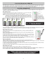
PLUG N’ GO (PNG): DEFAULT OPERATION
Upon initial power up, the DLM system automatically identifies the devices on the Local Network and the system then uses the Plug n’
Go™ configuration appropriate to the number of loads and types of devices on the DLM Local Network. If the LMPS is never configured,
the system defaults to PnG and ignores LMPS. If you tap any button, you will get no response until configured.
SETUP AND CONFIGURATION
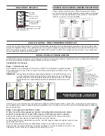
The LMPS-104 coordinates lighting for up to four moveable walls represented by 16 different configurations with each toggle button
representing the state of the wall (open or closed).
Step 1 Wall selection
To configure a wall, press and hold the button on the LMPS-104 for 10 seconds until the green
LED goes solid ON. This signals the LMPS that a wall is “active” (closed).
NOTE:
It is good practice to have buttons 1 through 4 on the LMPS-104 correspond to walls
1 through 4. For example, the first button should be pushed when wall 1 is closed, the
second button should be pushed when wall 2 is closed and the same for walls 3 and 4.
The corresponding Wall button LEDs should be illuminated for all walls that are closed.
Wall 1
Wall 2
Wall 3
Wall 4
Wall 1
Wall 2
Wall 3
Wall 4
Movable
Wa
ll
2
Active (Closed)
Active (Closed)
Room/
Partition 1
Closed
Room/
Partition 2
Closed
Movable
Wa
ll
1
Wall 1
Wall 2
Wall 3
Wall 4
Wall 1
Wall 2
Wall 3
Wall 4
Movable
Wa
ll
4
Active (Closed)
Active (Closed)
Room/
Partition 4
Closed
Room 5
Movable
Wa
ll
3
Room/
Partition 3
Closed
1
2
3
4
Once a wall is selected, the wall is now ready to be configured using Push n’ Learn (PnL). PnL is required to configure the new spaces
created by the presence of the wall. Enter into PnL mode from any device and configure each of the spaces.
Step 2 Enter Push n’ Learn
Using a pointed tool, press and hold the configuration button for 3 seconds, until the Red LED on the
switch begins to blink.
When you release the switch’s configuration button, the red LED on other communicating DLM Local
Network devices begins to blink.
The DLM Local Network is now in PnL mode. The Red LEDs continue to blink until you exit PnL mode.
All loads in the room turn OFF after entering PnL. After one second, one load turns ON. This is Load #1,
which is bound to switch button #1 as part of the Plug n’ Go factory default setting.
When in PnL with the LMPS in the local network, all devices will be un-bound
(Blue LEDs are OFF)
and
all devices will need to be selected and bound to the appropriate loads.
Step 3 Load selection
Press and release the configuration button to step through the loads connected to the DLM Local
Network. As each load turns ON select which devices (switch buttons and sensors) you want to configure for each space. The blue LED
will be ON for all switch buttons and sensors that are bound to this load.
To unbind a switch button from a load, press the switch button while its blue LED is ON. The blue LED turns OFF to indicate the button
no longer controls the load that is currently ON.
Pressing the switch button again while the load is ON rebinds the load to the button and the blue LED illuminates.
Step 4 Exit Push n’ Learn
Press and hold the configuration button until the red LED turns off, approximately 3 seconds.
Follow the steps above for each additional wall that is added as all devices will need to be configured in PnL.
To
Recall
a room
after the LMPS has been configured for all walls and spaces, press and hold the desired wall for 3 seconds.
Select the wall that is
closed by pressing the
corresponding button on
the LMPS for 10 seconds.
The green LED turns On to
indicate it is active (closed)
and ready to be configured.
IMPORTANT NOTE: LMSW-108 DOES NOT
WORK WITH PARTITIONING.
CAUTION:
TO CONNECT A COMPUTER TO THE DLM LOCAL NETWORK USE THE LMCI-100.
NEVER CONNECT THE DLM LOCAL NETWORK TO AN ETHERNET PORT
–
IT MAY DAMAGE COMPUTERS AND OTHER CONNECTED EQUIPMENT.


