


I N S T A L L A T I O N
©Vantage, 12/1/2016 / IS-0472-B
RadioLink® EasyTouch II ScenePoint DR — MODEL: RDR1XXX-XXXX
page 2 of 4
Mud Rings
If mud rings are specified on a job it is important to test the mud
rings for proper fit. Some mud rings run substantially smaller than
back boxes and are not large enough for the station. The
only
solution
is to test the fit first.
3-Way Switch Application
A ScenePoint DR Station may be used in any 3-way application.
When installing a ScenePoint DR station, as a 3-way switch, the
Red and Red/White (Loads Out) wires are not connected and are
properly capped-off.
Station Set Up in Software
InFusion:
In the
Project Explorer
click on
Style/Profile View
. Right
click on
Keypad Styles
and select
Add Keypad Style
. In the
Object
Editor
window fill in all the information for the keypad style
including the EasyTouch II
Button Shape.
Select SoftLine or
TrimLine plastic for ScenePoint stations. Remember to check or
uncheck the Auto Backlight check box to enable or disable this
built-in feature. Right click on button style and setup a button style
with the button color wanted. While still in Style/Profile View, right
click on LED Styles and fill in the appropriate information in the
Object Editor for EasyTouch II LEDs – Red/Green/Blue with ON
and OFF colors. Next select the room, then click on
Vantage
Objects
in the
Object Explorer
and expand
Stations, RadioLink
.
From the list of stations double click on the
ScenePoint DR Station
to place it in the room. In the Object Editor, name the station and
make sure it is on the correct RadioLink bus.
Configuration
RadioLink stations need to be configured to associate which
physical station goes with the station in software.
When the station is initially powered-up, the Status LED will blink
three times followed by a pause - this means the station is
powered correctly but not yet on the network.
Before
uploading
the file to the Vantage system, do the following: From Design
Center, click in the
Serial Number
section in the
Object Editor
and
type in the serial number. Manually enter the serial number for each
RadioLink station to match it with the corresponding
programming.
The serial number of each station is located on a permanent sticker
and a removable sticker* on the front of the station. Remove the
sticker with the number only and place on the Station Design
Report for easy reference when programming. The Main Controller
will add to its network and configure all the RadioLink stations that
it has serial numbers for. This may take several minutes depending
on the number of RadioLink stations on the network. The Status
LED will remain off when a station has been added to the network
and configured.
*If a serial number begins with “A”, do not use the letter “A” when
manually typing serial numbers into the Design Center file.
NOTE: A new feature with Design Center 2.3 and up is the ability
to configure RadioLink stations the same way WireLink stations are
configured, (e.g., 3-button press). When configuring stations,
Please note, if the
Exclude RadioLink Bus
check box, under
Settings
| System Preferences
, is not checked, all RadioLink stations go back
to non-programmed mode when the Configure Stations button on
the tool bar is clicked. The EasyTouch II station LEDs will all blink
between red and off while in configure station mode until
configured. After configuring stations and clicking the Configure
Stations button again to turn configure stations mode off, all
RadioLink stations need to log back on to the system before
working as programmed. Allow time for these stations to come
back online.
Interlocked, Independent or Shade Operation Modes
Interlocked Mode –
SWITCH ON BACK IN LEFT POSITION
:
This provides hardware interlock control between the two
relay loads. Both relays are never allowed to be ON
simultaneously. Interlock switch on the station must be set
to active/Interlocked
Independent Mode: –
SWITCH ON BACK IN RIGHT POSITION:
Each relay is controlled independent of the other. Both
relays may be on at the same time. Interlock switch on the
station must be set to inactive/non-Interlocked
Shade Mode: –
SWITCH ON BACK IN LEFT POSITION
:
For shade mode the Interlock switch on the station must be
set active/Interlocked. Limit switches must be properly
setup on shade motors. Station must be programmed as a
Shade Controller in Design Center
Changing Operation Mode of Station
If any station has been programmed as a Shade control or two
independent relays and the mode or operation is changed, set the
interlock switch and reset the station
before
re-programming in
Design Center. Please see
Reset
below.
Shade Controller
In this mode the station has the ability to track and set blinds to
specific positions.
Limit switches must already be set before doing
the following.
Once programmed as a shade controller in Design
Center the blind should be executed to fully OPEN and then fully
CLOSED positions. This
teaches
the station the limits of the blind it
is controlling. When the station has learned the full open and full
closed positions it can then be moved to any position wanted. For
example to move the blind to its middle position simply program a
task in Design Center to set the blind at 50%. It is also possible to
assign the blind to a slider on a TPT touchscreen. The blind may be
set to any position by moving the slider.
Self-Calibrating:
As stated above, when the shade is newly installed it must calibrate
itself by having the shade go to a limit (set on the motor) and then
go directly, without stopping, to the other limit. The station
measures the time
this travel takes and uses this time to determine
settings between the limits. Every time the shade goes directly
from one limit to the other limit it will
resave the travel time
preventing errors if the shade changes speed over time or new
fabric is installed or if the station is moved to a different shade etc.
Shades will travel at slightly different speeds when opening vs.
closing. This causes a normally small uncompensated error on the
position of the shade. If precise positioning is required, such as to
match positions of multiple adjacent shades, the ILT controller with
ILT motors should be used instead of this shade controller.
Reverse Shade:
NOTE: If the shade is moving in the wrong direction due to the
motor wires being reversed or the fabric is wound in the opposite
direction as expected on the roller, the direction can be reversed
by setting the Reverse Shade direction in Design Center preventing
the need to rewind the fabric or rewire the station.
Default Mode
The RadioLink EasyTouch II station has a default mode that
operates without programming or being connected to the Vantage
System. After a power outage the loads will be off even if they
were on before power was lost. If the station has power but
communication with the controller is lost the station will revert to
default operation, (i.e., toggling the load directly connected to the
station), however the interlock switch will still respond to its
current position, active or inactive. At final assembly, switches 1
through 3 control relay 1 and switches 4 and 5 control relay 2 until
programmed.
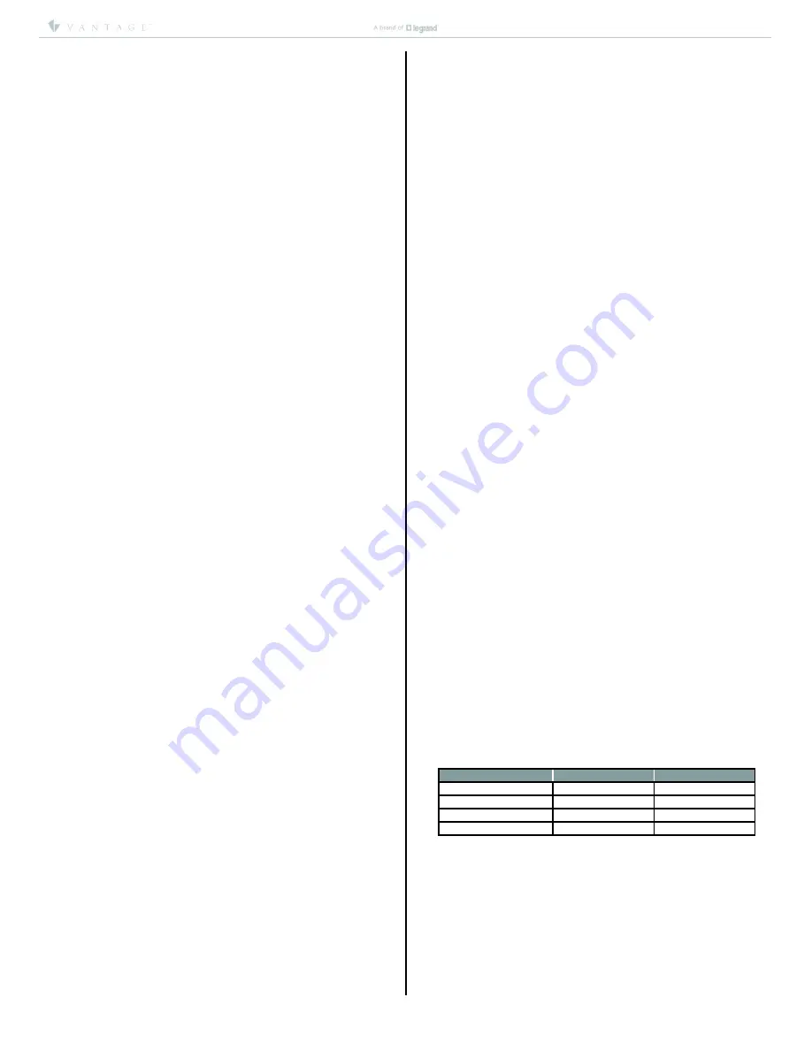
Default Button Control
Number of Buttons
Relay 1
Relay 2
2
Button 1
Button 2
3
Button 1
Buttons 2 & 3
4
Buttons 1 & 2
Buttons 3 & 4
5
Buttons 1, 2 & 3
Buttons 4 & 5
Default IR Mode
EasyTouch II ScenePoints have a built-in IR receiver. The default IR
mode that is active before the station is programmed or if the
station is offline is explained below. This is also dependent on the
status of the Interlock switch on the back of the station. When
Vantage IR Scene Code 230 is transmitted from the Vantage IR
Remote Control, local ScenePoint load one will toggle ON and OFF.
When Vantage IR Scene Code 231 is transmitted from the Vantage
IR Remote Control, local ScenePoint load two will toggle ON and
OFF. If the station is in Interlock mode then turning either load ON
will turn the opposite load OFF if it is already ON.


