

Fig 1: Parts in the box
Fig 2: Buttons, Status LED & Connections
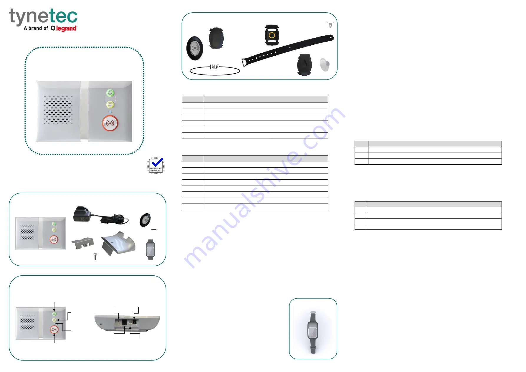
Fig 3:
Touch Pendant & Wearing Options
1.0 Parts in the box (see Fig 1)
#
Item
1
Reach IP At-Home Alarm unit
2
AC Adapter including UK & EU mains plug options
3
Connector Cover for mounting the Reach IP flat
4
Stand for mounting the Reach IP vertically
5
Screw for fixing the Stand or Connector Cover
6
Touch Pendant & Wearing Options or Wrist Worn Fall Detector
2.0 Buttons, Status LED & Connections (see Fig 2)
#
Function
⚫
Red Alarm Button: make an emergency call
Green Cancel Button: cancel an emergency call made in error
Yellow Function Button: toggle Home/Away mode (if enabled)
⚫
Black Power Button: on/off and enter Control Mode/Service Menu
⚫
Status LED: off is normal (
Green
no signal,
Red
alarm,
Amber
fault)
SUPPLY
5V DC input from AC Adapter
USB
Programming Port (factory use only)
ETHERNET Ethernet Port (factory use only)
3.0 Touch Pendant & Wearing Options (see Fig 3)
The Touch Pendant is a portable alarm trigger that can be worn around the neck, on
the wrist or clipped to a belt. The Pendant is already registered to the Reach IP unit
and ready to use, just fit the desired wearing option as described below;
⚫
Neck Cord:
lie the cord through one of the grooves on the rear on the Pendant then
slide the neck cord attachment into place. Note: smaller cord end marked
in Fig 3.
⚫
Wrist Strap:
feed the wrist strap (pattern side up) through the 2 slots in the wrist
strap attachment. Note: locate the pip marked
in the centre hole
in Fig 3.
Push the aluminium fixing stud through the hole marked
at the end of the strap.
⚫
Belt Clip:
simply clip into place on the rear of the Pendant. Note: the suction cup can
be fitted to the belt clip to stick the Pendant to a hard surface, e.g. a tiled wall.
An alarm call is made by simply pressing the button once, no further action is required.
The button will flash red to indicate a call has been transmitted, it will then flash green
as reassurance that the call has been received by the Reach IP.
4.0 Wrist Worn Fall Detector Option (see Fig 4)
The Fall Detector is a portable alarm trigger worn on the
wrist like a watch. To minimise false alarms, it should be
worn on the least dominant side; i.e. a right-handed
person should wear it on their left wrist and vice-versa.
The Fall Detector is already registered to the Reach IP
unit and ready to use.
An alarm call is made automatically if a fall is detected
or if the button is pressed
–
no further action is required.
The button will flash red then green as described above
for the Pendant.
5.0 Setting-up the Reach IP unit
1. Plug the AC Adapter into the mains supply.
2. Plug the AC Adapter Lead into the Reach IP unit SUPPLY port.
3. Switch the mains supply on at the wall, press and hold the
⚫
Power button for a
couple of seconds until the 3 front buttons illuminate briefly then release. The Red
Alarm button will remain lit if illumination is enabled (default) and the Status LED will
be lit green until a GSM signal is established then it will go out.
4. IMPORTANT: range test the Pendant or Fall Detector from all extremes of the home
- see section 6.4
5. Make an alarm call to the Alarm Receiving Centre (ARC) to check operation.
5.1 Making an Alarm Call
Press the
⚫
Alarm button and the unit will repeat
“
calling for help - please wait
”
.
When the message stops the alarm call will be made. It is possible to cancel the alarm
call by pressing the
Cancel button when the message is being played.
6.0 Control Mode & Service Menu
The Reach IP is normally in idle mode; Control Mode and Service Menu are ways of
easily reconfiguring the unit. The unit will return to idle mode after a change is made
or after 5 seconds of inactivity.
Control Mode Functions
Enter Control Mode by pressing the
⚫
Power button once, the unit will beep and the
and
buttons will illuminate. The Control Mode functions are listed below;
#
Control Mode Functions
⚫
Red Alarm Button: toggle Red Alarm Button illumination on/off
Green Cancel Button: change speech and sounds volume
Yellow Function Button: enter Service Menu (see below)
Service Menu Functions
Once in Control Mode, press and hold
until the unit announces the first Service
Menu function
“
add radio device
”
then release, the
button will be flashing. Press
the
button to sequentially step through the functions, press the
⚫
button to select
the required function. The Service Menu functions are listed below;
#
Service Menu Functions
1
Add Radio Device
2
Range Test Mode (also includes GSM Signal Strength Mode)
3
Delete Radio Devices
4
Home/Away Activity Function
6.1 Toggle Red Alarm Button Illumination
Press the
⚫
Power button to enter Control Mode then press and hold
⚫
until the unit
announces the new Red Button state e.g. if the illumination was ON then it will
announce
“
function is disabled
”
and illumination will now be off, if it was OFF then it
will announce
“
function is enabled
” and illumination will now be o
n.
6.2 Change Speech and Sounds Volume
Press the
⚫
Power button to enter Control Mode then then press and hold
until the
unit sounds a number of beeps to indicate its SPEECH volume setting - continue
holding
to cycle through the 3 settings and release on the required setting. Press
and hold
again within 5 seconds to change the SOUND level setting.
6.3 Add Radio Device
Press the
⚫
Power button to enter Control Mode then press and hold
until the unit
announces
“
add radio device
”
then release. Press the
⚫
button to confirm then
activate the radio device. The unit will sound a high beep if
it’s a new device
and
announce “
range test mode
”
- press
⚫
to confirm, or press
to step to the next
function, or press
to exit the mode and the unit will announce the next function.
Note: if the device already exists a low beep will sound.
Reach IP
At-Home Alarm
Screw for Stand/Cover
AC Adapter with
UK & EU Plugs
Touch Pendant &
Wearing Options
Connector
Cover
Stand
Reach IP unit
⚫
Red
Alarm Button
Green
Cancel Button
Yellow
Function
Button
⚫
Status
LED
Touch
Pendant
Neck Cord
Attachment
Wrist Strap
Attachment
Belt Clip
Attachment
⚫
Black
Power Button
Ethernet
Port
(factory use)
USB
Port
(factory use)
Supply
Port
User Guide
Wrist Strap
Neck Cord with
Safety Break
Aluminium
Fixing Stud
Suction
Cup
Rear Connector Area
Trusted Technology
Caring for People
OR
Fall Detector
Fig 4: Fall Detector


