


UPS user manual
Manuel de l'utilisateur de l'UPS
Utilizzo dell’UPS
36
OMD10074 REV. C
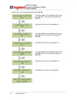
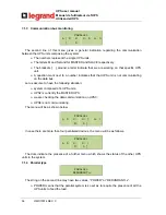
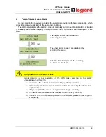
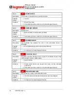
7.1.3 Communication bus monitoring
PARALLEL
1-[ M
]
2-
S
3- S
4- S
The second line of this menu gives a general indication regarding the communication
between the UPS units composing the system.
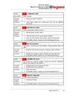
The numbers represent the single UPS units.
The letters M and S stand for MASTER and SLAVE respectively.
The brackets [ ] around a letter indicate that we are working on that specific UPS
unit.
A question mark next to a number indicates that that UPS unit is not communicating
on the data bus.
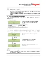
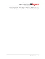
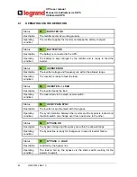
Let us assume to have the following situation:
system composed of 4 UPS units;
UPS2 is currently the MASTER UPS;
we are checking the data communication on UPS3;
UPS4 is not communicating.
The menu will be as shown below.
PARALLEL
1- S
2-
M
3- [
S ]
4- ?
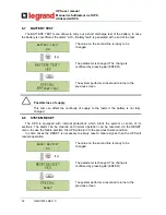
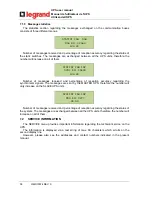
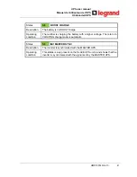
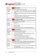
In case there are more than four paralleled devices, the menu will be as follows.
PARALLEL
1- S
2-
M
3- [
S ]
. . . .
The dots indicate the presence of a further menu which shows the status of the other UPS
units in the system.
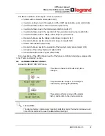
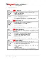
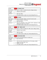
7.1.4 Parallel
type
PARALLEL
REx
The string on the second line may have two values, “POWER” or “REx”.
POWER means that the parallel system is so set as to require the presence of all the
UPS units to feed the load.
Summary of Contents for KEOR HP 100kVA
Page 55: ...UPS user manual Manuel de l utilisateur de l UPS Utilizzo dell UPS OMD10074 REV C 55 FRANÇAIS ...
Page 85: ...UPS user manual Manuel de l utilisateur de l UPS Utilizzo dell UPS OMD10074 REV C 85 ...
Page 87: ...UPS user manual Manuel de l utilisateur de l UPS Utilizzo dell UPS OMD10074 REV C 87 ...
Page 136: ...UPS user manual Manuel de l utilisateur de l UPS Utilizzo dell UPS 136 OMD10074 REV C ...


