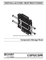
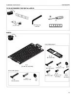
LEGRAND CHIEF CSPR Installation Instructions Manual Download Page 2

 CSPS/CSPR

Installation Instructions

2

DISCLAIMER

Legrand 

|

 AV and its affiliated corporations and subsidiaries 

(collectively “Legrand 

|

 AV”), intend to make this manual 

accurate and complete. However, Legrand 

|

 AV makes no claim 

that the information contained herein covers all details, 
conditions or variations, nor does it provide for every possible 
contingency in connection with the installation or use of this 
product. The information contained in this document is subject 
to change without notice or obligation of any kind. Legrand 

|

 AV 

makes no representation of warranty, expressed or implied, 
regarding the information contained herein. Legrand 

|

 AV 

assumes no responsibility for accuracy, completeness or 
sufficiency of the information contained in this document.
Chief® is a registered trademark of Legrand AV Inc.

DEFINITIONS

MOUNTING SYSTEM: 

A MOUNTING SYSTEM is the 

primary Chief product to which an accessory and/or component 

is attached.

ACCESSORY: 

AN ACCESSORY is the secondary Chief 

product which is attached to a primary Chief product, and may 

have a component attached or setting on it.

COMPONENT: 

A COMPONENT is an audiovisual item 

designed to be attached or resting on an accessory or mounting 
system such as a video camera, CPU, screen, display, 

projector, etc.

WARNING:  

A WARNING alerts you to the possibility of 

serious injury or death if you do not follow the instructions.

CAUTION:  

A CAUTION alerts you to the possibility of 

damage or destruction of equipment if you do not follow the 
corresponding instructions.

 IMPORTANT SAFETY INSTRUCTIONS

WARNING:  

Failure to read, thoroughly understand, and 

follow all instructions can result in serious personal injury, 
damage to equipment, or voiding of factory warranty! It is the 
installer’s responsibility to make sure all accessories are 
properly assembled and installed using the instructions 
provided.

WARNING:  

Failure to provide adequate structural strength 

for this accessory can result in serious personal injury or 
damage to equipment! It is the installer’s responsibility to 
make sure the structure to which this accessory is attached 
can support five times the combined weight of all equipment. 
Reinforce the structure as required before installing the 
accessory. The wall to which the accessory is being attached 
may have a maximum drywall thickness of 5/8” (1.6cm). Do 
not install drywall anchors into the seam between drywall 
pieces. 

WARNING:  

Exceeding the weight capacity can result in 

serious personal injury or damage to equipment! It is the 
installer’s responsibility to make sure the combined weight of 
all components attached to this accessory does not exceed 
20 lbs (9.07 kg). 

WARNING:  

Use this accessory only for its intended use as 

described in these instructions. Do not use attachments not 
recommended by the manufacturer.

WARNING:  

Never operate this accessory if it is damaged. 

Return the accessory to a service center for examination and 
repair.

WARNING:  

Do not use this accessory outdoors.

WARNING:  

RISK OF INJURY TO PERSONS! Do not use 

this accessory to support video equipment such as 
televisions or computer monitors.

--SAVE THESE INSTRUCTIONS--

Summary of Contents for CHIEF CSPR

Page 1: ...CSPR with Fusion wall mount and FCAV1U accessory Component Storage Panel Spanish Product Description German Product Description Portuguese Product Description Italian Product Description Dutch Product Description French Product Description CSPS CSPR ...

Page 2: ...of equipment if you do not follow the corresponding instructions IMPORTANT SAFETY INSTRUCTIONS WARNING Failure to read thoroughly understand and follow all instructions can result in serious personal injury damage to equipment or voiding of factory warranty It is the installer s responsibility to make sure all accessories are properly assembled and installed using the instructions provided WARNING...

Page 3: ...tion Instructions CSPS CSPR 3 DIMENSIONS CSPR 21 50 546 1 1 00 25 4 18 50 469 9 22 41 569 1 0 41 10 4 20 18 512 6 6 25 158 8 3 25 82 6 0 69 17 5 0 31 7 9 R0 07 1 9 10 15 257 8 0 86 21 9 0 46 11 8 0 57 14 6 CSPS ...

Page 4: ... Chave de bocas Chiave a punte aperte Steeksleutel Clé à fourche By Hand A mano Von Hand Com a mão A mano Met de hand À la main Hex Head Wrench Llave de cabeza hexagonal Sechskantschlüssel Chave de cabeça sextavada Chiave esagonale Zeskantsleutel Clé à tête hexagonale Pencil Mark Marcar con lápiz Stiftmarkierung Marcar com lápis Segno a matita Potloodmerkteken Marquage au crayon Drill Hole Perfora...

Page 5: ...ATION PARTS 1 2 12 7mm 2 5 32 security included A 1 Accessory wall plate With CSPR ONLY J 4 1 4 20 anchor K 4 1 4 20 x 1 3 4 L 4 1 4 With CSPS ONLY B 2 C 4 10 24 anchor D 4 10 24 x 1 1 4 E 4 10 F 4 10 24 x 3 4 G 2 10 24 x 1 2 security H 1 5 32 security Wall bracket ...

Page 6: ...ck side of wall is unfinished drywall must be installed to a minimum of one stud left and right of the studs being used to install the mount Drywall must be secured to studs with screws 12 on center Steel Stud 2 x 4 25ga minimum Stud type and structural strength must conform to the North American Specification for the Design of Cold Formed Steel Structural Members See hazard statement on page 2 36...

Page 7: ...lush behind wall See Figure 3 5 Slide plastic cap on anchor J towards wall until flange of cap is flush with wall See Figure 3 Figure 3 6 Snap off plastic straps on anchor at wall by pushing side to side snapping off straps level with flange of plastic cap See Figure 4 7 Repeat Steps 3 through 6 for the other mounting holes Figure 4 8 Place mount over anchors and align mounting holes on mount with...

Page 8: ...Figure 7 4 Holding plastic straps on anchor C pull anchor away from wall until channel rests flush behind wall See Figure 8 5 Slide plastic cap on anchor C towards wall until flange of cap is flush with wall See Figure 8 Figure 8 6 Snap off plastic straps on anchor at wall by pushing side to side snapping off straps level with flange of plastic cap See Figure 9 7 Repeat Steps 3 through 6 for the o...

Page 9: ...ey are on opposite sides of the brackets 13 Remove lower wall bracket from wall and drill two 1 2 holes at marked locations See Figure 12 14 Install two 10 24 anchors C into drilled holes following Steps 3 6 15 Reposition lower wall bracket B in mounting position and use two 10 24 x 1 1 4 Phillips pan machine screws D and two 10 washers E to secure wall bracket B to anchors C See Figure 12 Figure ...

Page 10: ...ory Plate Removal CSPR ONLY 1 Loosen four screws holding accessory wall plate A to wall brackets B See Figure 13 2 Grab handle and pull accessory wall plate A straight up until removed from wall brackets B See Figure 13 Figure 13 handle 1 x 4 or 2 ...

Page 11: ...Installation Instructions CSPS CSPR 11 ...

Page 12: ...952 225 6000 F 877 894 6918 952 894 6918 Europe A Franklinstraat 14 6003 DK Weert Netherlands P 31 0 495 580 852 F 31 0 495 580 845 Asia Pacific A Office No 918 on 9 F Shatin Galleria 18 24 Shan Mei Street Fotan Shatin Hong Kong P 852 2145 4099 F 852 2145 4477 8800 002943 Rev01 2019 Legrand AV www legrandav com 05 19 ...

Reviews: