background image

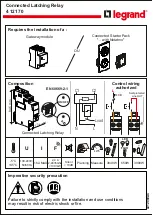
Connected Latching Relay
4 121 70

LE12069AC

Composition

EN 60669-2-1

Requires the installation of a :  

Connected Starter Pack

"... with Netatmo" 

Gateway module

OU

84.5 mm

17.8 mm

ON/OFF

Control wiring

authorized

Connected Latching Relay

F

16A MAX

2,4 à

2,4835Ghz

<100 mW

-5°C

+45°C

100-240V~

50/60Hz

U

I

650W

3000W

3840W

LED

FLUO

1
2
3
4
5
6
7
8
9
10
11
12
13
14
15
16
17
18
19
20
21
22
23
24
25
26
27
28
29
30

oooooooooooooooo

oooooooooooooooo

ooooooooooo

oooooooooooooo

ooooooooooo

ooooooooooooooo

oooooooo

ooooooooooooo

oooooo

oooooooooooooo

ooooooooooo

oooooooooooooooo

oooooooooooooo

ooooooooooo

oooooooooooooo

oooooooooooo

ooooooooooooooo

oooooooooooooo

ooooooooooo

oooooooooooooooo

oooooooooooooo

ooooooooooo

oooooooooooooo

oooooooooooooooo

ooooooooooo

oooooooooooooooo

oooooooooooooo

ooooooooooo

oooooooooooooo

oooooooooooo

1

2

3

4

5

6

7

8

9

10

11

12

13

14

15

16

17

18

19

20

21

22

23

24

25

26

27

28

29

30

1

oooooooooooooooo

oooooooooooooooo

ooooooooooo

oooooooooooooo

ooooooooooo

ooooooooooooooo

1

2

3

4

5

6

7

11

12

13

14

15

16

17

18

19

20

21

22

23

24

25

26

27

28

29

30

10

9

8

Jan

Feb

Mar

Planning Measure

kWh

< 10dB

L

N

Load

C1

C2

Silent

L

Self-protected

 Line OUT

C1

C2

C1

C2

MCB

Failure to strictly comply with the installation and use conditions    
may result in risk of electric shock or fire.

Imperative security precaution

Summary of Contents for 4 121 70

Page 1: ...ooo oooooooooooooo ooooooooooo oooooooooooooo oooooooooooo ooooooooooooooo oooooooooooooo ooooooooooo oooooooooooooooo oooooooooooooo ooooooooooo oooooooooooooo oooooooooooooooo ooooooooooo oooooooooooooooo oooooooooooooo ooooooooooo oooooooooooooo oooooooooooo 1 2 3 4 5 6 7 8 9 10 11 12 13 14 15 16 17 18 19 20 21 22 23 24 25 26 27 28 29 30 1 oooooooooooooooo oooooooooooooooo ooooooooooo ooooooooo...

Page 2: ...ith appropriate rating is required MAX 2x 2 5mm 6mm N L Load MAX 2x 1 5mm 2 5mm C1 C2 MIN 0 8Nm MAX 1 4Nm C1 C2 N L Load Preparation connection Turn off the power at general circuit breaker N neutral blue L Line everything but blue and green yellow Line after contact usually purple orange C1 C2 N Load L 4 121 70 16AX I O OFF ON push buttons junction box push buttons C1 C2 N Load L 4 121 70 16AX I O...

Page 3: ... and hold the Gateway module settings button or in the center of the General Scenario Wireless Command until the LED turns green then release the button 3 OR OR Option associate a wireless on wall switch with Netatmo Press the main button of the Connected Latching Relay until the LED is slowly blinking blue and then release it A B Hold down the wireless remote button and tap until the LED turns fix...

Page 4: ...ress and hold the center of the push button until the LED lights up in orange then briefly press on the center to confirm the reset EU SIMPLIFIED DECLARATION OF CONFORMITY The undersigned Legrand declares that the radio equipment listed on this instruction sheet are compliant to the directive 2014 53 UE The full text of the EU declaration of conformity is available at the following website www legra...

Reviews: