Performance Verification
DA18000-OM-E Rev A
7-3
d.
Remove the
÷
2 attenuator from the coaxial cables.
e.
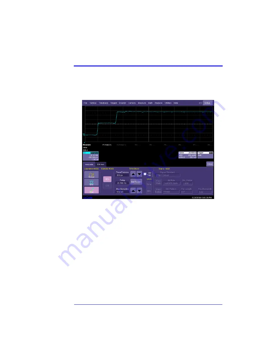
From the menu bar, select
Timebase
(Figure 7-1).
f.
Set the WE 9000 to output a differential step. This sampling oscilloscope is only used
to provide power to the ST-20 TDR pulse generators
g.
Initialize the TDR by touching the
TDR Main
tab.
Figure 7-1. Timebase Menu
h.
Connect the ST-20 TDR coaxial cable from Channel 1 of the WE 9000 via the LPA–K
adapter to Channel 1 of the SDA 18000. Be sure to properly torque all connectors
(8 in.-lbs.).
i.
Set the SDA 18000 to Channel 1 and the timebase to 500 ps/div and 60 GS/s. Set the
scope to trigger on Channel 1, and edge triggering to positive slope.
j.
Set math trace F1 to the
Ptrace mean
of Channel 1 (Figure 7-2).
Summary of Contents for DA18000
Page 1: ...LeCroy DA18000 Differential Amplifier Instruction Manual December 2006 ...
Page 4: ...iv DA18000 OM E Rev A BLANK PAGE ...
Page 10: ...DA18000 Differential Amplifier 2 2 DA18000 OM E Rev A BLANK PAGE ...
Page 12: ...DA18000 Differential Amplifier 3 2 DA18000 OM E Rev A BLANK PAGE ...
Page 22: ...DA18000 Differential Amplifier 6 4 DA18000 OM E Rev A BLANK PAGE ...
Page 34: ...DA18000 Differential Amplifier A 2 DA18000 OM E Rev A BLANK PAGE ...


