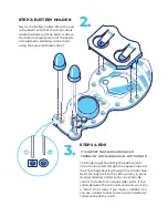
Next is the battery holder. Place the part
in the board such that the small cutout
where the battery will be slid in is above
the bottom striped portion of the board.
Complete all 4 soldering connections
using the same method as Step 1.
2.
STEP 2: BATTERY HOLDER
3.
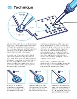
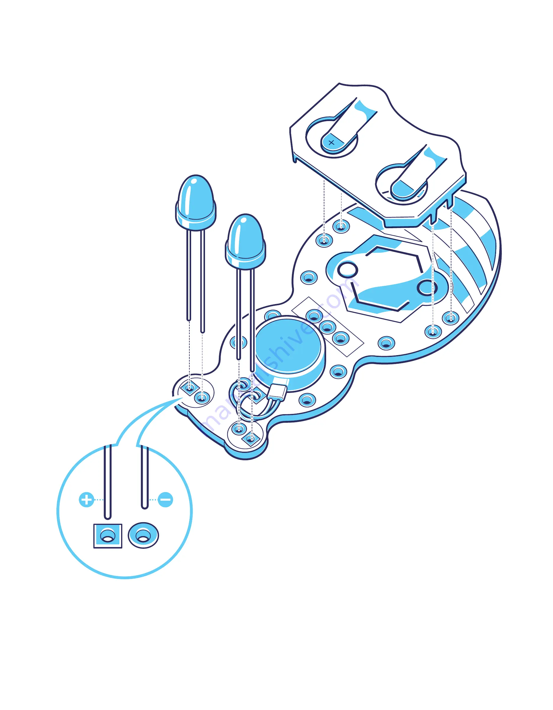
The longer leg of the LED is the positive lead.
Place the long leds through the square hole and
the short (negative) leg through the circular hole.
Bend the legs back so the LEDs will stay in place
during soldering. Solder each connection. Be
careful to create four unique solder joints. If the
solder between the two joints connects you have
a “short”. Don’t worry if you make a mistake. You
can use a solder sucker to remove the additional
solder and redo the joints.
STEP 2: LEDS
IT IS IMPORT THAT LEDS ARE PLACED
CORRECTLY OR YOUR BUG WILL NOT TURN ON
Summary of Contents for Jitterbug
Page 1: ......

