background image

7

10

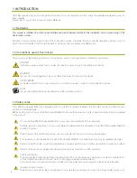
3. LEAF MICROINVERTER M500-S

General information on LEAF M500-S Microinverter: names and functions of  the parts.

Messa a terra

M5 Screw

Protective Vent

Robust Venting

PV Input

MC-4 Connector

AC Output

Standard RST connector

Backover Slot

Fastening Slot

Backover Hole

Easy Handling

Heatsink

LEAF Design

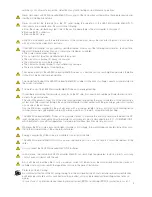
3.1 Label

The label of the microinverter contains all the useful information for its identification, including the serial number, the release of the 
software and the symbols whose meaning is given in the table below.

3.2 Wiring

When a monitoring system is required, the installer shall inform the client about the best suited configuration based on the system 
architecture and clients needs.
Each microinverter is an independent production unit, safe and efficient: it can then be installed, monitored and controlled 
independently from the others.

The serial number shown on the label is used in the mapping procedure for relating each microinverter with its location in the 
plant, so that it can uniquely identified during the phases of configuration and diagnostic: this operation is fundamental for the 
proper use of the monitoring system (if any).

Caution hot surface: do not touch.

Read the instructions before to use and to install.

Risk of electric shock. Presence of dangerous voltage inside the enclosure.

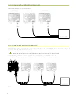
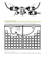
Realize the connections as shown in figure 4.2.

Inspection Box

4.2.1 Connection without WIELAND distribution units

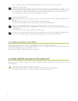
Each distribution unit can accommodate a maximum of 4 connection cables: up to 3 AC lines from microinverters and up to 2 
cables for connecting to the distribution network.

As depicted in fig.4.3 and 4.4, several arrangements are possible when more distributors are in use.

4.2.2 Connection with WIELAND distribution unit

Fig. 3.1

Fig. 3.2

Fig. 4.2

Fig. 4.3

Always use the supplied cap to close the unused connection points on the AC distribution units.

Inspection Box

LE-1615A-0000000200-C-52010-11

Serial Number

Summary of Contents for M500-S

Page 1: ...MICROINVERTER M500 S Installation Manual...

Page 2: ...November 2014 Copyright LEAF SpA...

Page 3: ...ting the AC BUS 4 2 1 Connection without WIELAND distribution units 4 2 2 Connection with WIELAND distribution unit 4 3 Connecting to the PV panels 4 4 Connecting the AC distribution network Grid 9 9...

Page 4: ...t may affect the proper functioning of the device HOT SURFACE It indicates operations that may cause burns and serious damage in case of contact with hot surfaces NOTE It is used to highlight particul...

Page 5: ...nd connection of the metal housing when required by the rules of installation of the photovoltaic system must be carried out through the appropriate threaded socket marked with the grounding symbol an...

Page 6: ...the microinverter may cause a voltage drop of a value such as to impair the connection to the distribution network to ensure the efficient operation of the system the voltage drop in the AC wiring ha...

Page 7: ...l inform the client about the best suited configuration based on the system architecture and clients needs Each microinverter is an independent production unit safe and efficient it can then be instal...

Page 8: ...nected to the distribution network through the protective equipment defined by local regulations WARNING If exposed to sunlight the solar modules will always exhibit DC voltage at their electrical ter...

Page 9: ...sequence of operations Connecting the AC bus of the PV system at all the LEAF M500 S microinverters Connecting all the LEAF M500 S microinverters to their respective panel or to the pair of solar pane...

Page 10: ...n cables up to 3 AC lines from microinverters and up to 2 cables for connecting to the distribution network As depicted in fig 4 3 and 4 4 several arrangements are possible when more distributors are...

Page 11: ...ed in series as shown in figure 4 5 Plug the DC connectors until the latch The DC connectors between the photovoltaic module and the LEAF Microinverter M500 S must not be opened during operation of th...

Page 12: ...rk through the protective equipment defined by local regulations All the parts of the plant must be kept dry before and during installation and connection 5 REMOVING A LEAF MICROINVERTER M500 S Isolat...

Page 13: ...re grounding Grounding is ensured by the dedicated conductor on the AC side its connection should be performed based on natio nal laws for grounding wires The use of the ground connection of the metal...

Page 14: ...IN 1 INSTALLATION MAP CLIENT DATA INSTALLER DATA ORIENTATION Insert geographical orientation and roof slope Company 4 3 Roof section N ___ A Te In 2 5 14 Address City Company Address City...

Page 15: ...nge 48 3 48 3 nominal power Low Voltage Fault Ride Through LVFRT Yes Max Output Fault Current 5 6 A Internal Input Transient Overvoltage Protection Yes Max Units per Branch Circuit 9 15 for 20 32A bre...

Page 16: ...ntries across the globe The mission of VeNetWork is to promote business culture via the funding and development of new manufacturing companies and service providers that will generate economic profess...

Reviews: