Leadtek Amor C101 User Manual Download Page 22

More Security, More Convenience


22 


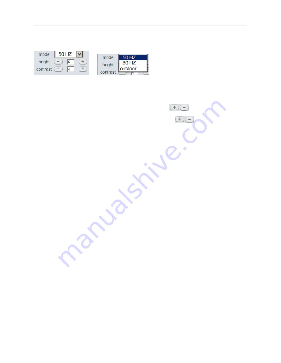
Mode, Bright, Contrast Settings 


                                        Figure 4.0 

Mode

: This is work mode optional, 50HZ/60HZ for the users who use 50HZ/60HZ frequency, outdoor for the 

users who want to use this camera to monitor toward outdoor environment     

NOTE

: This camera normally should be used in a indoor environment 

Bright

: Set the parameters to adjust the image quality of video. Click


to adjust the value 

Contrast

: Set the parameters to adjust the image quality of video. Click 


to adjust the value 

Default all

: Click it to set all the parameters back to factory setting. 

NOTE

: If you login the camera, there is no video displayed, and the parameter of bright/contrast is blank, 

maybe you can try to click “default all” to set the parameters back to factory setting to get live video. 


NOTE: 

For Operator, if you click other menus which operator don’t have the right to operate it, there will be a 

pop-up of login interface (Figure 2.6), please input the user name / password for at least 3 times to login again.


2.9 For Administrator 

Details see

 Settings as Administrator

 (details3.1-3.22). 


Summary of Contents for Amor C101

Page 1: ...C101 IP Wireless Wired Camera User Manual...

Page 2: ...S 23 3 2 NETWORK SETTINGS 28 3 3 BASIC NETWORK SETTINGS 29 3 4 WIRELESS LAN SETTINGS 30 3 5 ADSL SETTINGS 31 3 6 UPNP SETTINGS 31 3 7 DDNS SERVICE SETTINGS 32 3 8 P2P SETTINGS 35 3 9 SYSTEM SETTINGS 3...

Page 3: ...office Also controlling and managing images are simple by clicking the website through the network 1 1 Features Powerful high speed video protocol processor High sensitivity 1 4 CMOS sensor Picture t...

Page 4: ...e 2 Infrared LED For night vision 3 LENS CMOS sensor with fixed focus lens Default is 6mm 3 6mm optional 4 Network Indicator LED If there is network activity the LED will blink 5 Microphone Build in m...

Page 5: ...he factory default Parameter Please keep the power on when do RESET 1 3 3 Back View Figure 1 3 There are some stickers at the bottom such as MAC address sticker QC sticker etc If your camera does not...

Page 6: ...al panel will keep on The yellow led will keep flash and the Indicator led at the front of the camera will flash The indicator LED can be controlled by software Figure1 4 1 6 Software Installation Att...

Page 7: ...More Security More Convenience 7 Figure1 6 Figure1 7 Figure1 8 After this done the icon IP Camera Tool will be displayed on desktop automatically...

Page 8: ...adapter may cause damage to your IP Camera IP Camera terminal shall be installed in an indoor environment where the rain or snow could not pour it Do not touch the lens of the IP Camera at will The op...

Page 9: ...the result field as shown in Figure 1 9 3 The IP Cameras installed within LAN do not share the same subnet with the monitoring PC A prompt as shown in result field prompt Subnet doesn t match double c...

Page 10: ...which camera is it Sometimes if there is no IP address showed on the IP Camera tool maybe it s blocked by firewall then add the MAC ID to the router and give it a fixed IP or add the MAC ID as a trus...

Page 11: ...ddress Here gateway is the LAN IP of your router DNS Server IP address of IPS network provider You can also set it s the same as the Gateway NOTE You can find the Subnet Mask Gateway DNS Server from y...

Page 12: ...he network cable 2 1 1 4 Refresh Camera List Refresh camera list manually 2 1 1 5 Flush Arp Buffer When cable network and wireless network of the device are fixed IP address There is a problem you may...

Page 13: ...e and password the Sign In interface will pop up There are three models to login 1 Active Mode For IE Browser available in IE6 0 or above explorer 2 Server Push Mode available in Firefox Safari and Go...

Page 14: ...howed in the center of the screen or even just a black screen please try to enable the ActiveX options of IE security settings Please do the follow steps 1 Close the firewall of your computer 2 Change...

Page 15: ...via Control Panel Internet Explorer enter to Security setting If you allowed the ActiveX running but still could not see live video only a Red Cross in the center of the video and the device status l...

Page 16: ...ox Google Browser and sign in Server Push Mode doesn t support ActiveX so some functions are not available such as Play Stop Record Audio Talk etc if you want to use these functions please use IE brow...

Page 17: ...Interface as below NOTE There are 3 levels of users Visitor Operator Administrator if you login with different users the use authority is different See 3 11 User Settings Figure 7 4 2 7 For Visitor W...

Page 18: ...m CH1 to CH9 NOTE If you want to view 4 9 channels you should set the Multi Device firstly See 3 1 Multi Device Settings Status of Channels There are 9 icons at the bottom of the UI which show the sta...

Page 19: ...ay date and time on the video Disabled Click this one means clear the OSD Color Can set the OSD text color as black yellow red white blue etc Add time stamp on record Click this there will be time OSD...

Page 20: ...to red color click it again it will stop record The record file will be saved to the folder you set Figure 9 5 Figure 9 7 Click it to collect the sound around the camera if you plug a earphone or a sp...

Page 21: ...ns as below Figure 3 8 Audio Video Settings Figure 3 9 Audio buffer Click this icon it will show five numbers which means 1 2 3 4 5 seconds buffer of audio Reversal Click this icon to see the reversal...

Page 22: ...adjust the image quality of video Click to adjust the value Default all Click it to set all the parameters back to factory setting NOTE If you login the camera there is no video displayed and the par...

Page 23: ...e 4 3 Multi Device Settings This camera can support max 9 channels device at the same time 3 1 1 Set Multi Device in LAN In the Multi Device Settings page you can see all devices searched in LAN The 1...

Page 24: ...More Security More Convenience 24 after all done please click Submit Figure 4 4 Click Live Video and then select to see four channels or click to see nine channels Figure 4 5...

Page 25: ...e been set DDNS successfully View 3 7 DDNS Service Settings And also these cameras work well with DDNS Login the first camera by DDNS domain name and port this camera will be as the host camera Figure...

Page 26: ...me DDNS domain name just set different port number for each different camera Figure 4 8 Note Add the other camera in the same way Click submit to add all of them Click Live Video and then select to se...

Page 27: ...choose correct bin file then click Submit to do upgrading NOTE Before doing upgrade via Browser please make sure the IP Camera Tool of your computer could find the camera s IP Attention Please must ke...

Page 28: ...pop up a prompt select OK all the parameter will be returned to factory settings and the device will reboot Figure 5 1 3 1 5 Reboot Device Click Reboot the device will pop up a prompt select OK then...

Page 29: ...ettings from IP Camera Tool Figure 2 3 Figure 5 3 If you don t know Subnet Mask Gateway DNS Server Please check the Local Area Connection Status of your computer it contains all these information step...

Page 30: ...may change it to another port number such as 85 3 4 Wireless Lan Settings Figure 5 7 1 Make sure the router is wireless router 2 Make sure the Wi Fi antenna installed 3 Make sure whether there is encr...

Page 31: ...through ADSL directly you can enter the ADSL username And password obtained from ISP Figure 5 9 3 6 UPnP Settings Click UPnP Settings to choose Using UPnP to Map Port Figure 6 0 Select it and click Su...

Page 32: ...ror information So we recommend you do port forwarding manually in your router Details see Figure 6 4 6 8 3 7 DDNS Service Settings Figure 6 1 There are 2 options Manufacturer s DDNS This domain is pr...

Page 33: ...he camera will reboot wait about 30 seconds Figure 6 4 Make sure the Subnet Mask Gateway DNS Server is the same as your router Set Port Forwarding in the router This is the most important step Set por...

Page 34: ...router 2 Choose Firewall select Virtual Servers 3 Input the port except 80 and IP address then click save NOTE The port and IP address should be the same as Camera Figure 6 6 DLINK 1 Login the router...

Page 35: ...DDNS status from the camera as below and get the link of DDNS for internet view Step Login System Device Info Figure 6 8 3 8 P2P Settings You will be able to see the camera from all over the world Yo...

Page 36: ...1 Device Info You can find the information about Device ID Firmware Version Embedded Web UI Version Alias Alarm Status DDNS Status UPnP Status Figure 7 0 3 10 Device name Default device name is C101 Y...

Page 37: ...7 2 Figure 7 3 3 12 Users Settings Eight accounts are acceptable for this system Here you can set the user names and password as Administrator Operator or Visitor the permission for them as below Vis...

Page 38: ...nnect to the internet and more slower when departed 3 Been extinguished Keep OFF 3 14 Backup Restore Figure 7 6 1 Backup Backup IP Camera all the Parameter if you want to save all the current settings...

Page 39: ...etc 3 15 Other Settings Figure 7 8 Figure 7 9 Here you can configure some additional functions such as Motion Detection Alarm IO Linkage Schedule FTP Upload Alarm Mail Alert Record Path etc 3 16 Mail...

Page 40: ...ese following errors when you click Test Please check whether the information you filled in are incorrect Make sure all of them are correct and try it again 1 Can not connect to the server 2 Network E...

Page 41: ...settings Then click Test You will see the following picture Figure 8 3 If it prompts error information as follows 1 Can not connect to the server Please check FTP Server is correct or not 2 Network Er...

Page 42: ...ect Armed If enable Motion Detect Armed it will record and make a sound of alarm when there is motion detection triggered Figure 8 5 After enable motion detect armed if there is motion triggered the A...

Page 43: ...it s an alarm input device choose Alarm Input Armed to enable it when it s an output device choose IO Linkage on Alarm to enable it Figure 8 7 There are two options for Trigger Level Figure 8 8 High W...

Page 44: ...cture or control the internal relay output If you link an external alarm device with Pin3 and Pin4 when select Alarm Input Armed Figure 8 7 external alarm is enabled Output pins The output pins can be...

Page 45: ...d once alarmed Cancel it there will be no sound once alarmed Record on Alarm If you want the camera do recording for every alarm choose Record on Alarm to enable it If you do not want the camera do re...

Page 46: ...ath Here you can set the manually record path Click then start manually record the record file will be saved to the specified path here set Alarm Record Path Here you can set the alarm record path Whe...

Page 47: ...enience 47 Figure 9 8 3 21 Server Push Mode For Safari FireFox Google Browser Choose Server Push Mode login the camera you will see the main user interface as below Figure 9 9 NOTE Server Push Mode do...

Page 48: ...other functions are the same as ActiveX Mode For IE Browser 3 22 Sign in mobile phone If you are using a mobile phone choose Sign in mobile phone login the camera you will see the main user interface...

Page 49: ...eway of the camera Keep them in the same subnet of your computer Figure 2 3 4 1 3 IP Address configuration Check whether IP address of the IP camera server shares the same subnet as your work station...

Page 50: ...rator input the IP address of the camera manually 4 1 9 I can t find multi device settings and record icon Record and multi device function are controlled by activeX controller So if you use Safari Fi...

Page 51: ...4 Choice of switch or hub Use a switch for multiple IP Camera Servers rather than a HUB 4 1 15 How to register an account from DDNS web You can enter http www dyndns com and register an account more d...

Page 52: ...0Base T 100Base TX Ethernet Port Supported Protocol TCP IP DHCP SMTP HTTP DDNS UPNP PPPoE FTP DNS UDP GPRS Wireless LAN Support wireless network Wi Fi 802 11 b g n WEP Encryption Disable 64 bit 128 bi...

Page 53: ...ur issue please contact our company This user manual is based on the latest version of our camera System Firmware 17 1 2 22 If your cameras do not support some special functions showed in the manual p...

Reviews: