


EM422S Digital Stepper Drive User Manual
Page | 8
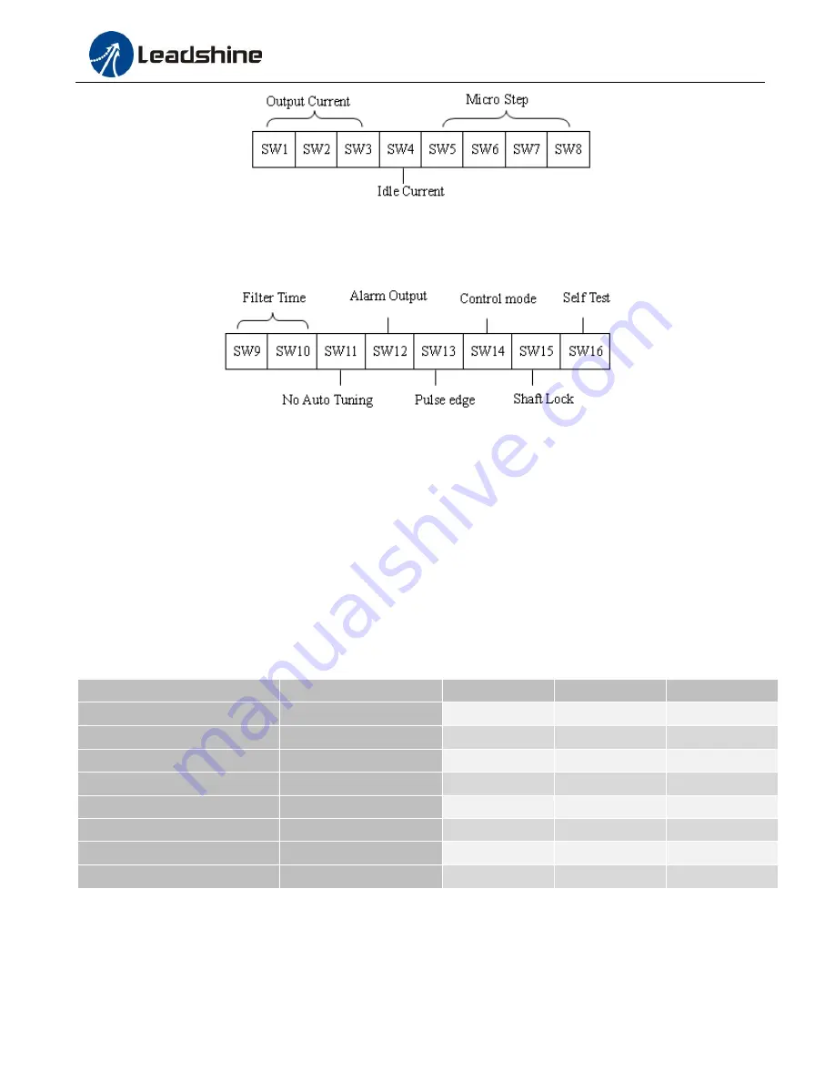
The second 8-bit DIP switch is located on the top (DIP switch selector 2 in figure 2), and used to configure settings of
control command filtering time, motor auto-configuration, fault output impedance, pulse active edge, control mode,
lock shaft, and self-test as shown below:
7.1 Output Current Configuration
(SW1-3)
The EM422S has 8 micro step settings which can be configured through DIP switch SW1, SW2 and SW3.
For a given stepper motor, higher drive output current will make it output higher torque, but at the same time cause
more heating for both the motor and drive. Therefore, output current is generally set to be such that the motor will not
overheat for long time operation. Since parallel and serial connections of motor coils will significantly change resulting
inductance and resistance, it is therefore important to set drive output current depending on motor phase current, motor
leads and connection methods. Phase current rating supplied by motor manufacturer is important in selecting drive
current; however the selection also depends on leads and connections.
The first three bits (SW1, 2, 3) of the DIP switch are used to set the dynamic current. Select a setting closest to your
motor’s required current.
Peak Current
RMS Current
SW1
SW2
SW3
0.3A
0.21A
ON
ON
ON
0.5A
0.35A
OFF
ON
ON
0.7A
0.49A
ON
OFF
ON
1.0A
0.71A
OFF
OFF
ON
1.3A
0.92A
ON
ON
OFF
1.6A
1.13A
OFF
ON
OFF
1.9A
1.34A
ON
OFF
OFF
2.2A
1.56A (default)
OFF
OFF
OFF
7.2 Idle Current Configuration (SW4)
The SW4 of an EM422S is used to set output current percentage when motor is standstill. Idle current percentage will
be set to 50% at OFF position, and 90% at ON position. When the driven stepper motor is idle (no movement) for 0.4
second, the output current of EM422S will be automatically reduced to the configured percentage.


