EM415S Digital Stepper Drive User Manual
Motion Control Products Ltd.
Tel.: (+44) 01202 599922
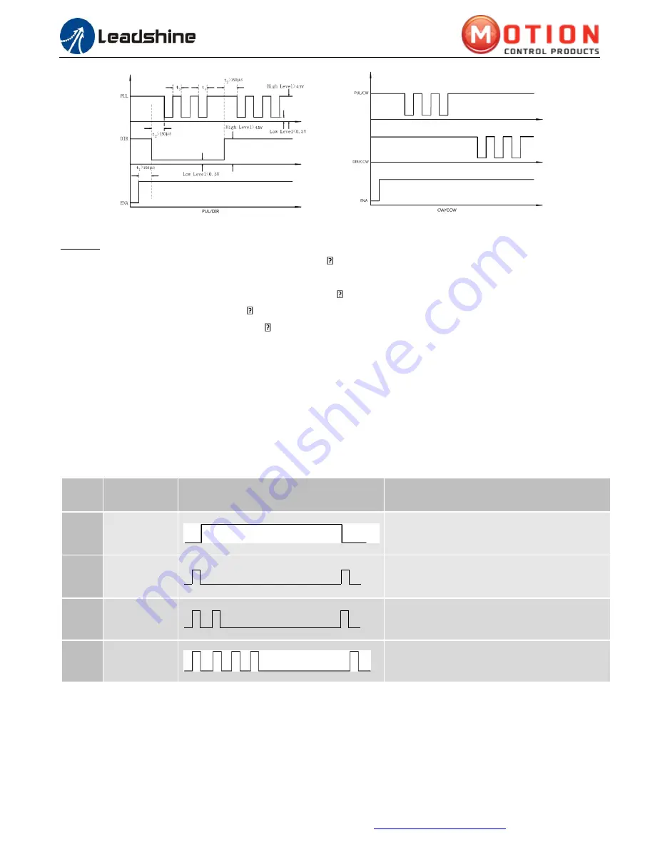
Figure 13
Sequence chart of control signals
Remark:
a)
t
1
: ENA must be ahead of DIR by at least 150 s. Usually, ENA+ and ENA- are NC (not connected). See
“Connector P1 Configurations” for more information
b)
t
2
: DIR must be ahead of PUL effective edge by 150 s to ensure correct direction
c)
t
3
: Pulse width not less than 72 s, duty cycle recommend 50%
d)
t
4
: Low level width not less than 72 s
e)
For control signals, both PUL,DIR and ENA are activated by rising edges in default
11.
Protection Functions
EM415S incorporates are built with over-voltage and over-current error protections. When it is under error
protection, the red LED light will blink for 1 or 2 or 4 times in a period of 3 seconds. If fault output connection is
connected, the impedance mode between ALM+ and ALM-
will be changed (See “Fault Output Configuration”
section for detail).
Priority
Time(s) of
Blink
Sequence wave of red LED
Description
1
st
Always on
The drive was short-circuited or burned out.
1
st
1
Over-current protection activated when peak
current exceeds the limit.
2
nd
2
Over-voltage protection activated when drive
working voltage is greater than 42VDC
3
rd
4
Motor cable error or not connected to the motor.
Figure 14
Error Protections
When over-current and over-voltage protections are activated, the motor shaft will be free or the red LED blinks.
Reset the drive by restart it to make it function properly after removing above problems.


