12
ELD2-RS70** User Manual
Chapter 3 Wiring
Warning
⚫
The workers of participation in wiring or checking must possess sufficient ability do this job.
⚫
The wiring and check must be going with power off after five minutes.
Caution
⚫
Ground the earth terminal of the motor and driver without fail.
⚫
The wiring should be connected after servo driver and servo motor installed correctly
3.1 Wiring
3.1.1 Wire Gauge
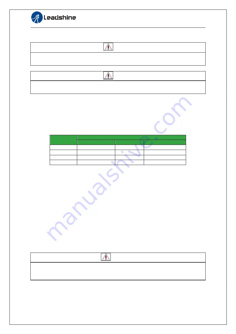
(1)Power supply terminal TB
● Diameter:
Driver
Wire diameter (mm
2
/AWG)
Vdc,GND
U.V.W
PE
ELD2-*7010
2.627/AWG13
2.627/AWG13
2.1/AWG14
ELD2-*7015
2.627/AWG11
2.627/AWG11
2.1/AWG14
ELD2-*7020
5.26/AWG10
5.26/AWG10
2.1/AWG14
ELD2-*7030
8.37/AWG8
8.37/AWG8
2.1/AWG14
● Grounding: The grounding wire should be as thick as possible, drive servo motor the PE terminal
point ground, ground resistance <100 Ω.
●Use noise filter to remove external noise from the power lines and reduce an effect of the noise
generated by the servo driver.
● Install fuse (NFB) promptly to cut off the external power supply if driver error occurs.
(2) The control signal CN1 feedback signal CN2
● Diameter: shielded cable (twisting shield cable is better), the diameter ≥ 0.14mm
2
(AWG24-26), the
shield should be connected to FG terminal.
● Length of line: cable length should be as short as possible and control CN1 cable is no more than 3
meters, the CN2 cable length of the feedback signal is no more than 20 meters.
● Wiring: be away from the wiring of power line, to prevent interference input.
●Install a surge absorbing element for the relevant inductive element (coil),: DC coil should be in
parallel connection with freewheeling diode reversely; AC coil should be in parallel connection with
RC snubber circuit.
Attention
⚫
Match the colors of the motor lead wires to those of the corresponding motor output terminals
(U.V.W)
⚫
Never start nor stop the servo motor with this magnetic contactor.


