background image


D

D

C

C

S

S

8

8

1

1

0

0

V

V

2

2


D

D

i

i

g

g

i

i

t

t

a

a

l

l


D

D

C

C


S

S

e

e

r

r

v

v

o

o


D

D

r

r

i

i

v

v

e

e

r

r


M

M

a

a

n

n

u

u

a

a

l

l


R

R

e

e

v

v

1

1

.

.

0

0


Tel: (86)755-26434369 


10


  Website: www.leadshine.com 

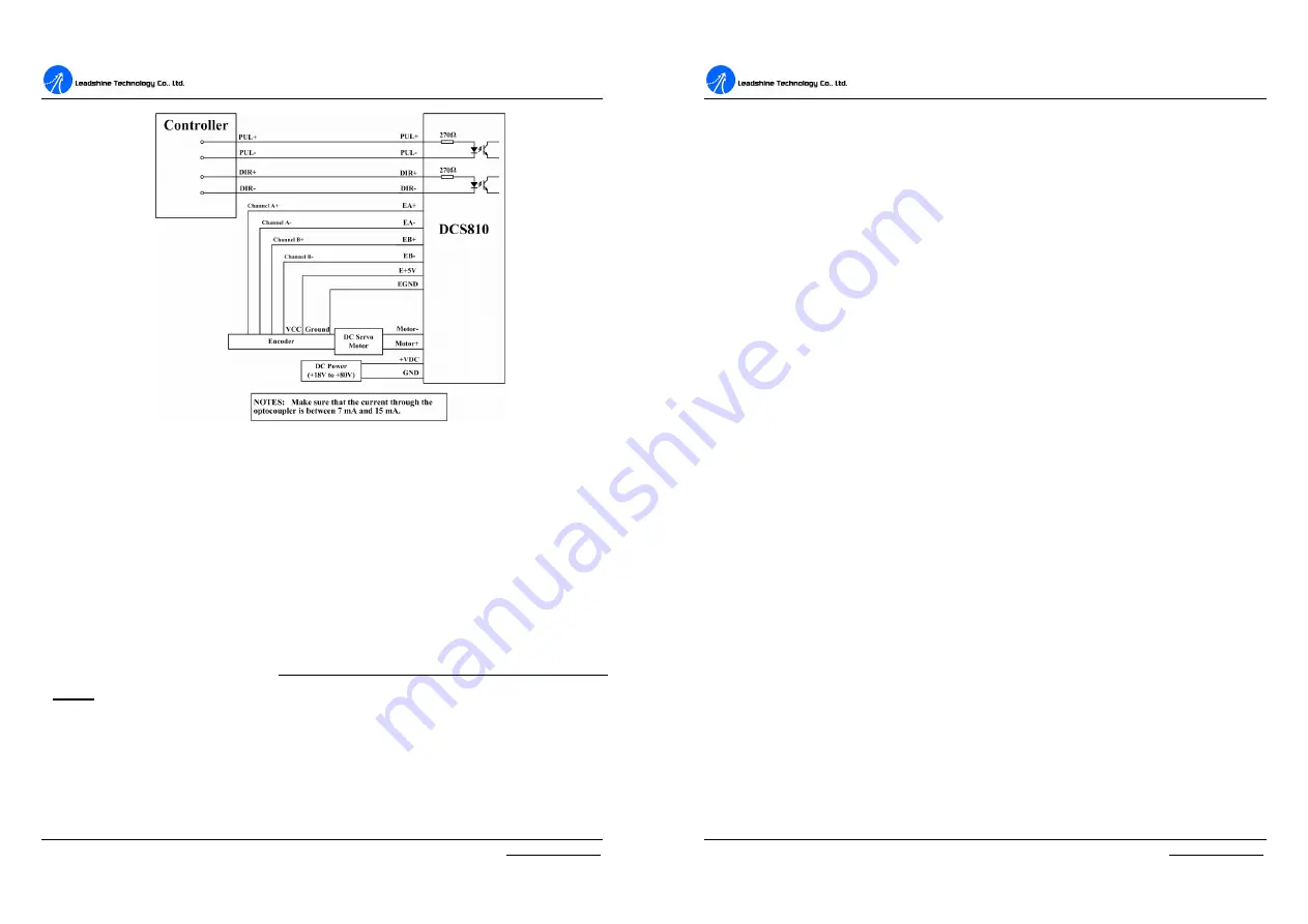
Figure 3-10: Typical connection (Differential control signal and differential encoder.) 

4. Servo Setup

Before you start the servo, you can follow the below steps. 

Install Encoder 

If  your  motor  has  no  encoder,  you  must  have  an  encoder  (more  than  200  lines) 

properly  mounted  on  the  motor  before  you  start.  And  please  assemble  the  encoder 

according  to  its  factory  manual. 

Here,  we  recommend  use  differential  encoder 

again.

 If you do have to use a single-ended encoder, please use shielded cables and 

separate  encoder  signal  cable  from  interference  sources,  such  as  motor  wires  and 

power wires at least 5 cm. 


D

D

C

C

S

S

8

8

1

1

0

0

V

V

2

2


D

D

i

i

g

g

i

i

t

t

a

a

l

l


D

D

C

C


S

S

e

e

r

r

v

v

o

o


D

D

r

r

i

i

v

v

e

e

r

r


M

M

a

a

n

n

u

u

a

a

l

l


R

R

e

e

v

v

1

1

.

.

0

0


Tel: (86)755-26434369 


11


  Website: www.leadshine.com 

Prepare Power Supply 

Regulated or Unregulated Power Supply 

Both  regulated  and  unregulated  power  supplies  can  be  used  to  supply  the  driver. 

However, unregulated power supplies are preferred due to their ability to withstand 

current  surge.  If  regulated  power  supplies  (such  as  most  switching  supplies.)  are 

indeed  used,  it  is  important  to  have  large  current  output  rating  to  avoid  problems 

like current clamp, for example using 4A supply for 3A motor-driver operation. On 

the other hand, if unregulated supply is used, one may use a power supply of lower 

current rating than that of motor (typically 50%

70% of motor current). The reason 

is that the  driver draws current  from the power supply  capacitor of the  unregulated 

supply  only  during  the  ON  duration  of  the  PWM  cycle,  but  not  during  the  OFF 

duration.  Therefore,  the  average  current  withdrawn  from  power  supply  is 

considerably  less  than  motor  current.  For  example,  two  3A  motors  can  be  well 

supplied by one power supply of 4A rating. 

Selecting Supply Voltage 

The  DCS810V2  can  actually  operate  within  +18V  to  +80VDC,  including  power 

input fluctuation and back EMF voltage generated by motor coils during motor shaft 

deceleration.  The  rated  voltage  of  the  motor  is  an  important  parameter  when 

selecting  supply  voltage.  Generally  speaking,  do  not  use  a  power  supply  voltage 

more than 5 volts of the rated voltage of the motor. Higher voltage may cause bigger 

motor  vibration  at  lower  speed,  and  it  may  also  cause  over-voltage  protection  or 

even driver damage.   

Prepare Controller 

Prepare a controller with pulse and direction signals. However, the DCS810V2 has a 

built-in  motion  controller  for  self-test  and  Servo  Tuning.  The  built-in  motion 

controller can generate control signal with trapezoidal velocity profile. 

Summary of Contents for DCS810V2

Page 1: ... to any products herein to improve reliability function or design Leadshine does not assume any liability arising out of the application or use of any product or circuit described herein neither does it convey any license under its patent rights of others Leadshine s general policy does not recommend the use of its products in life support or aircraft applications wherein a failure or malfunction ...

Page 2: ...ower Supply 11 Selecting Supply Voltage 11 Prepare Controller 11 System Connections and Noise Prevention 12 Wire Gauge 12 Contents Tel 86 755 26434369 II Website www leadshine com Cable Routing 12 Twisted Wires 12 Cable Shielding 13 System Grounding 13 Power Supply Connection 13 5 Tuning the servo 14 Testing the servo 14 Tuning the Servo 15 6 PC window based Tuning Using ProTuner 17 Introduction 1...

Page 3: ...ications performances of DC servo systems using the DCS810V2 are better than those of digital AC servo systems in velocity precision noise stability or at least as good as those of digital AC servo systems However the cost of the DCS810V2 stays at the price line of stepping driver namely far lower than those of AC servo drivers Compared to the DB810 50V the DCS810V2 can accept differential control...

Page 4: ...ons l Small size surface mount technology Applications Suitable for a wide range of equipments and instruments such as mini type engraving machines jet ink machines etc It performs better in equipments desired for low noise high velocity high precision and high reliability D DC CS S8 81 10 0V V2 2 D Di ig gi it ta al l D DC C S Se er rv vo o D Dr ri iv ve er r M Ma an nu ua al l R Re ev v1 1 0 0 T...

Page 5: ... O 3 VDC 18 TO 80VDC power input I 4 GND Power ground GND RS232 Communication Connector Pin Signal Description I O 1 NC Not connected 2 5V 5V power only for STU O 3 TxD RS232 transmit O 4 GND Ground GND 5 RxD RS232 receive I 6 NC Not connected More about PUL DIR EN Signals Pin Function Details PUL PUL Pulse signal In single pulse pulse direction mode this input represents pulse signal 4 5V when PU...

Page 6: ...xed level Figure 3 1 PUL DIR and CW CCW settings Control Signal Connections The DCS810V2 can accept differential and single ended inputs including open collector and PNP output The DCS810V2 has 2 optically isolated logic inputs to accept line driver control signals These inputs are isolated to minimize or eliminate electrical noises coupled onto the control signals Recommend use line driver contro...

Page 7: ...Figure 3 4 or Figure 3 5 If the encoder drains more than 50mA use an external DC supply and connect it as Figure 3 6 or Figure 3 7 Figure 3 4 The DCS810V2 supplies the Figure 3 5 The DCS810V2 supplies the differential encoder directly single ended encoder directly Figure 3 6 Using external DC power supply Figure 3 7 Using external DC power to to supply the differential encoder supply the single en...

Page 8: ...re indeed used it is important to have large current output rating to avoid problems like current clamp for example using 4A supply for 3A motor driver operation On the other hand if unregulated supply is used one may use a power supply of lower current rating than that of motor typically 50 70 of motor current The reason is that the driver draws current from the power supply capacitor of the unre...

Page 9: ... Se er rv vo o D Dr ri iv ve er r M Ma an nu ua al l R Re ev v1 1 0 0 Tel 86 755 26434369 13 Website www leadshine com along with the ground or chassis wire if available Cable Shielding All signal wires should be bundled and shielded separately from driver power and motor power wires Power wires should also be bundled and shielded When grounding a shield the rule of thumb is to do so at the source...

Page 10: ...nputs and try again If it s Encoder Error please check encoder and its wirings and then try again If it still doesn t work after you followed all of the previous steps please contact us at tech leadshine com If the red LED is off and the motor is normal then you can start to tune the servo with selected tool ProTuner and STU are available for the DCS810V2 D DC CS S8 81 10 0V V2 2 D Di ig gi it ta ...

Page 11: ...s UNDER DAMPED then increase Kd or decrease Kp or Ki 3 If servo system is CRITICALLY DAMPED then stop tuning and download the parameter settings to the driver s EEPROM 4 If servo system is OVER DAMPED then decrease Kd or increase Kp or Ki D DC CS S8 81 10 0V V2 2 D Di ig gi it ta al l D DC C S Se er rv vo o D Dr ri iv ve er r M Ma an nu ua al l R Re ev v1 1 0 0 Tel 86 755 26434369 17 Website www l...

Page 12: ...click Next to continue installation The user can enter user s information in the following window See Figure 6 3 After entering the user s information click Next to select installation folder where you would like to install the ProTuner See Figure 6 4 D DC CS S8 81 10 0V V2 2 D Di ig gi it ta al l D DC C S Se er rv vo o D Dr ri iv ve er r M Ma an nu ua al l R Re ev v1 1 0 0 Tel 86 755 26434369 19 ...

Page 13: ...essfully See Figure 6 8 Figure 6 6 Installation information summarization D DC CS S8 81 10 0V V2 2 D Di ig gi it ta al l D DC C S Se er rv vo o D Dr ri iv ve er r M Ma an nu ua al l R Re ev v1 1 0 0 Tel 86 755 26434369 21 Website www leadshine com Figure 6 7 Installing the ProTuner Figure 6 8 Finish installation Note Leadshine also offers special version ProTuner which does not need installation P...

Page 14: ...coder inputs and try again If it s Encoder Error please check encoder and its wirings and then try again If it still doesn t work after you followed all of the previous steps please contact us at tech leadshine com If the red LED is off and the motor is normal then you can start to tune the servo with ProTuner However we recommend you see the following contents before starting tuning D DC CS S8 81...

Page 15: ...he menu bar Tuning The user can choose one or two drop down menu s by clicking Tuning including CurrentLoop and PositionLoop l CurrentLoop It is used to configure current loop parameters according to different motor In the tuning window User can set Kd Ki and I test D DC CS S8 81 10 0V V2 2 D Di ig gi it ta al l D DC C S Se er rv vo o D Dr ri iv ve er r M Ma an nu ua al l R Re ev v1 1 0 0 Tel 86 7...

Page 16: ...r Can be set from 1 to 255 Position FollowErrLimit Position Following Error Limit The limit of the difference between commanded position and the actual measured position When position following error reaches Position Following Error Limit parameter setting in the driver the protection will be activated Encoder Lines Encoder Line Count The DCS810V2 supports single ended and differential ended incre...

Page 17: ...Website www leadshine com Error v_err Position Following Error p_err Current Feedback i_bak Velocity Feedback v_bak Position Feedback p_bak Current Command i_ref Velocity Command v_ref Position Command p_ref i_err Current Following Error The difference between commanded current and the actual measured current v_err Velocity Following Error The difference between commanded velocity and the actual m...

Page 18: ...nd all error events can be reset by clicking Erase All button D DC CS S8 81 10 0V V2 2 D Di ig gi it ta al l D DC C S Se er rv vo o D Dr ri iv ve er r M Ma an nu ua al l R Re ev v1 1 0 0 Tel 86 755 26434369 31 Website www leadshine com Figure 6 16 Error check window OverCurrent Over current Protection Protection will be activated when continuous current exceeds 20A OverVoltage Over voltage Protect...

Page 19: ...utput becomes the new torque set point There are some important differences in the tuning process and application of these two approaches Position around Velocity This mode is most common in contouring application where a position trajectory must be tracked very closely The velocity loop provides additional stiffness and keeps the dynamic position errors minimal since the system now reacts to not ...

Page 20: ...meters with the standard version if they use the drivers with Leadshine s DCM5xxxx DC servo motors If you use the DCS810V2 with DC servo motors from other manufacturers and current loop tuning is needed Please use ProTuner to tune the current loop at first Follow the steps below for tuning the driver with the ProTuner Current Loop Tuning Example If user uses Leadshine DCM series motor they don t n...

Page 21: ... 37 Website www leadshine com Kp and back off Our purpose is to make the green curve the actual current a little higher than the red curve the target So we decrease Kp to 4500 4200 and until the actual value is exactly over the target value Figure 6 23 Current loop tuning with with Ki 0 and increasing Kp Step 4 Now Kp is relative good enough But there is still gap between the green curve and the r...

Page 22: ...o o D Dr ri iv ve er r M Ma an nu ua al l R Re ev v1 1 0 0 Tel 86 755 26434369 39 Website www leadshine com Velocity and Position Loop Tuning Before trying to manage the velocity and position loop parameters Vp Vi Kp Kp Kaff see page 25 connect the system as figure 6 19 Then set self test motion parameter and select the display curve in digital scope as figure 6 25 figure 26 TraceTime affects the ...

Page 23: ...is hard to rotate move and the motor generates big noise you should lower down Vp Kp If it is easy to rotate move and even the drive goes into protection mode the red LED blinks you should increase Vp Kp D DC CS S8 81 10 0V V2 2 D Di ig gi it ta al l D DC C S Se er rv vo o D Dr ri iv ve er r M Ma an nu ua al l R Re ev v1 1 0 0 Tel 86 755 26434369 41 Website www leadshine com Step 2 Increase Vp unt...

Page 24: ...p to 800 for quick response Kp 500 Position following error 644 Kp 800 Position following error 404 D DC CS S8 81 10 0V V2 2 D Di ig gi it ta al l D DC C S Se er rv vo o D Dr ri iv ve er r M Ma an nu ua al l R Re ev v1 1 0 0 Tel 86 755 26434369 43 Website www leadshine com Figure 6 31 Increase Kp to 1200 for quick response Figure 6 32 Increase Kp to 1800 for quick response Now the system has been ...

Page 25: ... Se er rv vo o D Dr ri iv ve er r M Ma an nu ua al l R Re ev v1 1 0 0 Tel 86 755 26434369 45 Website www leadshine com 7 Using Tips Sequence Chart of Control Signals In order to avoid some fault operations and deviations PUL DIR and EN should abide by some rules shown as the following figure Figure 7 1 Sequence chart of control signals Notes a t1 EN must be ahead of DIR by at least 5µs Usually ENA...

Page 26: ... feedback signals will activate this protection RED LED will turn on five times within each periodic time 5 s Note When power up the motor shaft needs to be stalled or rotated several revolutions to activate this protection if the motor encoder wire s not connected Position Following Error Protection When position following error reaches Position Following Error Limit parameter setting in the driv...

Page 27: ...ect Option Archives the archives window will appear as figure 7 2 To save the current parameter to a file type in the path and file name in the edit box and then click ToDisk button See figure 7 2 for more detail Figure 7 2 Save parameter to a file Type in path and file name Save to file D DC CS S8 81 10 0V V2 2 D Di ig gi it ta al l D DC C S Se er rv vo o D Dr ri iv ve er r M Ma an nu ua al l R R...

Page 28: ...shine for warranty service and Leadshine shall pay for return of products to customer WARRANTY LIMITATIONS Leadshine makes no other warranty either expressed or implied with respect to the product Leadshine specifically disclaims the implied warranties of merchantability and fitness for a particular purpose Some jurisdictions do not allow limitations on how long and implied warranty lasts so the a...

Page 29: ...ca areas 86 755 2640 9254 for Europe America areas Fax 86 755 2640 2718 Email sales leadshine com Technical Support Tel 86 755 2641 8447 and 86 755 2647 1129 Fax 86 755 2640 2718 Email tech leadshine com and vic leadshine com Leadshine U S A Address 25 Mauchly Suite 318 Irvine California 92618 Tel 1 949 608 7270 Fax 1 949 608 7298 Web http www leadshineUSA com Email sales leadshineUSA com and supp...

Reviews: