Leadingtouch TM-19 User Manual Download Page 16


www.leadingtouch.com


16

/

27


NOTE: 

OSD menu default is enabled. 

Control                                                                                    Function


Menu/Exit                                                           

Display/exits the OSD menus. 

                                                                            1. Enter contrast of the OSD. 

2. Increase value of the adjustment item. 

3. Select item counter-clockwise. 

                                                                            1. Enter brightness adjustment. 

2. Decrease value of the adjustment item. 

3. Select item counter-clockwise. 

Select                                                                     

Selects the adjustment items from the OSD menus. 

Power Switch                                                       

Switches the power of the monitor. 


OSD Menu Function 

To Display and Select the OSD Functions: 

1 Press the Menu key to activate the OSD menu. 

2 Use 

△ or ▽

  to move counter-clockwise through the menu. Press the Enter key, the parameter 

will be highlighted when selected. 

3 To quit the OSD screen at any time during the operation, press the Menu key. If no keys are 

pressed for a short time period, the OSD automatically disappears. 

NOTE: 

The OSD screen will disappear if no input activities are detected for 45 seconds.


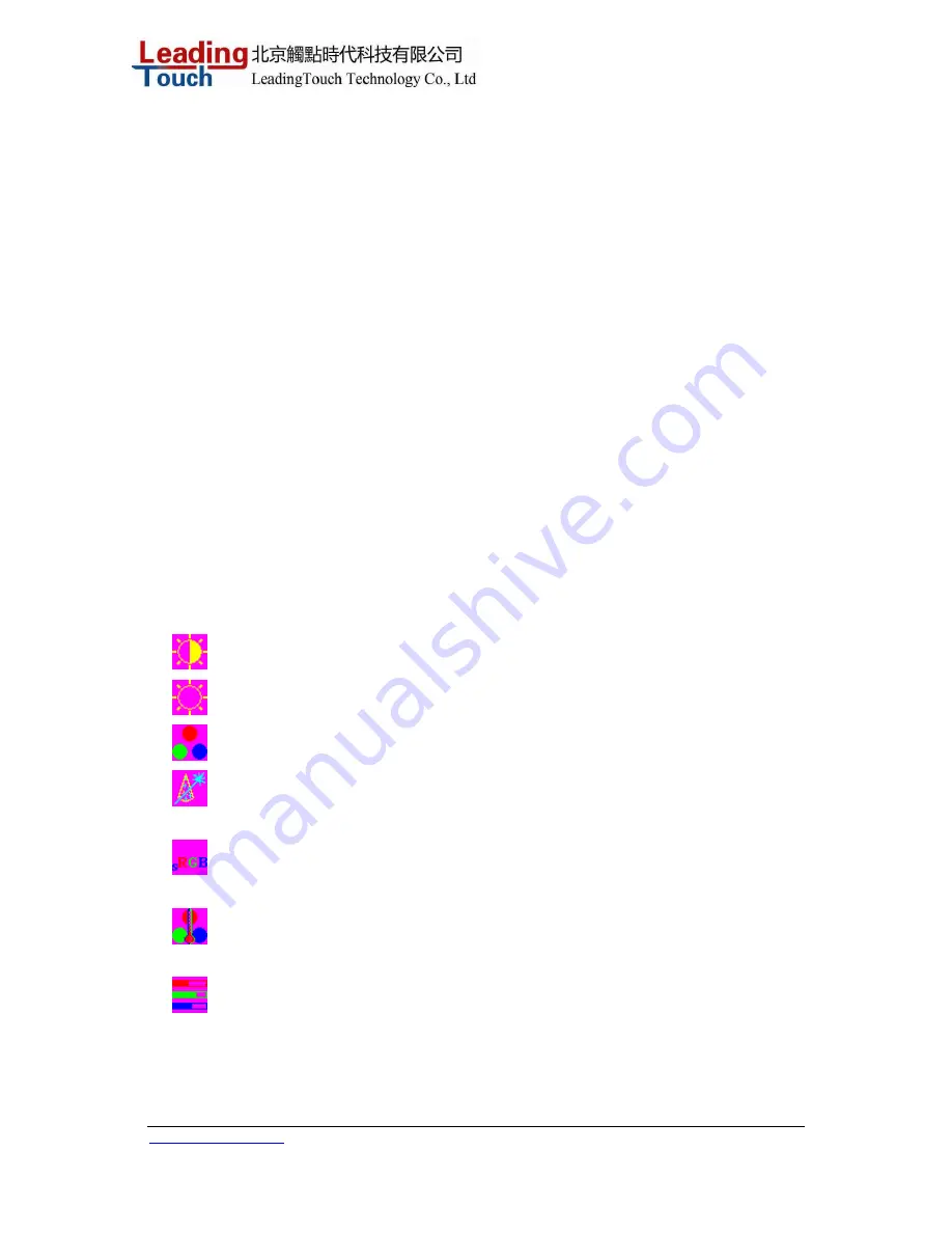
Control Description 

    Contrast         

Increases or decreases contrast


  Brightness   

Increases or decreases brightness


  Color


RGB color adjustment


  Auto color


Automatically adjust RGB color. 


    sRGB

:      

Select  sRGB standard color 


Color Temperature              In this menu you can select one of the default color temperatures 

(9300

o

K, 7500

o

K, 6500

o

K, 5000

o

K, 4200

o

K )   

    User                           

Press the OSD button Up and Down or set color values 

individually using the "USER" option. To define the color values 

individually, select the "USER" option. You can switch between 

the setting options for R/G/B (red, green and blue foreground) 

using the OSD direction button. Select and specify the desired 

Summary of Contents for TM-19

Page 1: ...r User Guide TM 19 19 LCD Rear Mount Touchmonitor REV A LeadingTouch Technology Co Ltd HuiLongGuan LongXiang industrial center ChangPing Beijing China Tel 86 51090978 http www leadingtouch com Fax 86...

Page 2: ...iver Software 8 Chapter 3 15 OPERATION 15 About Touchmonitor Adjustments 15 Using the On Screen Display OSD Menus 15 OSD Menu Function 16 Preset Modes 18 Power Management System 18 Chapter 4 20 TROUBL...

Page 3: ...performance are Plug Play compatibility and OSD On Screen Display controls Precautions Follow all warnings precautions and maintenance as recommended in this user s manual to maximize the life of your...

Page 4: ...www leadingtouch com 4 27 Wall mountable with optional bracket Cable strain reliefs for all cables For full Product Specifications refer to Appendix C...

Page 5: ...NSTALLATION AND SETUP This chapter discusses how to install your LCD touchmonitor and how to install Leadingtouch TouchSystems driver software Unpacking Your Touchmonitor Check that the following 10 i...

Page 6: ...uchscreen serial RS232 cable or the touchscreen USB cable but not both to the rear side of the computer and the other end to the LCD monitor Tighten by turning the two thumb screws clockwise to ensure...

Page 7: ...www leadingtouch com 7 27 Product Overview Main Unit Rear View Side View...

Page 8: ...n Windows starts If Windows detects your touchmonitor follow the instructions on the screen to install a generic plug and play monitor Refer to the appropriate section for driver installation instruct...

Page 9: ...uch com 9 27 5 Click Next and select the com port which the touchscreen connected 6 Then press Install to continue installation 7 After install finished you need restart the system and save all your w...

Page 10: ...rs for the specified communication connectors RS232 USB Follow these steps to install Leadingtouch 1 Put the Leadingtouch CD to CD ROM 2 Change directory to Win9598me OR Win2000_XP 3 Double click the...

Page 11: ...sful installtion of the drver reboot the system first adn then click calibrate 2 Click the center of the bull s eyes cross with finger according to the prompt 3 click all the bull s eyes press Enter o...

Page 12: ...following programmer 1 Click Start programmer Leadingtouch Serial USB 2 Click Calibration 1 3 Line test Test the touchscreen 1 Clear clear all the lines in the test screen 2 Exit quit test mode 1 4 S...

Page 13: ...elease indicates the response when your finger leavvs the touchs panel Drag line mode DoubleClick Drag support double click and drag mode double click range indicates the double click area the unit is...

Page 14: ...uch 1 6 About About leadingtouch 1 7 Rescan Leadingtouch usb controller After you replus Leadingtouch usb touchscreen controller please use this tools rescan the touchscreen 1 8 Uninstall Leadingtouch...

Page 15: ...choose 1280 x 1024 resolution Operating in other resolutions will degrade video performance For further information please refer to Appendix A All adjustments you make to the controls are automaticall...

Page 16: ...it the OSD screen at any time during the operation press the Menu key If no keys are pressed for a short time period the OSD automatically disappears NOTE The OSD screen will disappear if no input act...

Page 17: ...D H Position Moves the OSD position horizontally on the screen When the button is pressed the OSD control menu will move to the right side of the screen Likewise when the button is pressed the OSD con...

Page 18: ...or is capable of storing up to 7 user modes The only condition to store as a user mode is the new display information must have 1 KHz difference for horizontal frequency or 1 Hz for vertical frequency...

Page 19: ...d transfer it to low frequency signal then Demodulator demodulate the low frequency signal and output the Transfer Stream TS to Decode System Control System separate the program stream PS which come f...

Page 20: ...it is not damaged Check for bent pins on the cable connectors Ensure that your computer and video card are properly configured Consult video card documentation Out of Range display Check to see if the...

Page 21: ...ch com 21 27 Check and reconfigure the display mode of the vertical refresh rate of your graphic card to make it compatible with the LCD display Touch doesn t work Make sure cable is securely attached...

Page 22: ...t increase it Input Video 19 LCD 640 x 480 VGA Transforms input format to 1280 x 1024 800 x 600 SVGA Transforms input format to 1280 x 1024 1280 x 1024 XGA Displays in Native Resolution The native res...

Page 23: ...ng of input video pixels to LCD pixels As an example the pixel in column 45 and row 26 of the input video is in column 45 and row 26 of the LCD For the case when the input video is at a lower resoluti...

Page 24: ...k or insert anything inside the ventilation slots 5 It is important that your touchmonitor remains dry Do not pour liquid into or onto your touchmonitor If your touchmonitor becomes wet do not attempt...

Page 25: ...www leadingtouch com 25 27...

Page 26: ...with the following standard video modes VGA 640 x 480 60 Hz 640 x 480 72 Hz 640 x 480 75 Hz 640 x 350 70 Hz 720 x 400 70 Hz SVGA 800 x 600 56 Hz 800 x 600 60 Hz 800 x 600 72 Hz 800 x 600 75 Hz XGA 102...

Page 27: ...nd if not installed and used in accordance with the instructions may cause harmful interference to radio communications However there is no guarantee that interference will not occur in a particular i...

Reviews: