


4. BEFORE YOU BEGIN MEASURING
28
●
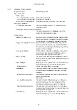
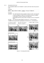
In 3D Assist Mode (L/R DUAL) (Option)
When F•1 3D ASIST A/C ch is set to ON, reclocked signals for INPUT SDI A and INPUT
SDI C are output from OUTPUT SDI A/B and OUTPUT SDI C/D, respectively.
When F•2 3D ASIST B/D ch is set to ON, reclocked signals for INPUT SDI B and INPUT
SDI D are output from OUTPUT SDI A/B and OUTPUT SDI C/D, respectively.
4.5
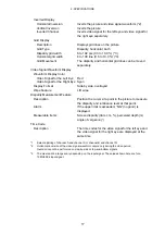
External Sync Signal Input
On the video signal waveform display, vector display, and optional phase difference display,
you can apply an external sync signal to display waveforms (except when the video format is
1080p/60, 1080p/59.94, or 1080p/50). Apply a tri-level sync signal or an NTSC/PAL black
burst signal to the external reference input connectors.
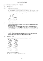
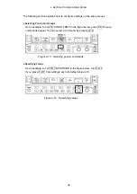
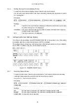
Figure 4-7 External sync signal input connectors
●
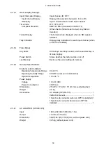
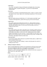
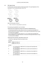
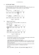
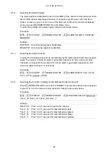
Loop-Through
As shown in the figure below, the external sync signal input connectors are loop-through.
Apply the input signal to one of the two connectors, and terminate the other connector at 75
Ω
, or connect it to another 75
Ω
device. If you connect to another device, be sure to
terminate the other device's connector at 75
Ω
.
Connect cables with a characteristic impedance of 75
Ω
to the input connectors.
Figure 4-8 Loop-through
●
Setting External Synchronization
When you are using an external sync signal, set EXT REF to ON on the video signal
waveform display, vector display, or optional phase difference display. On other displays,
waveforms are displayed in sync with the SDI signal regardless of the EXT REF setting.


