4. BEFORE YOU BEGIN MEASURING
27
4.4
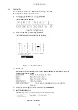
SDI Signal Output
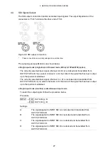
The SDI output connectors transmit reclocked input signals. The output impedance of the
connectors is 75
Ω
. Terminate the other end at 75
Ω
.
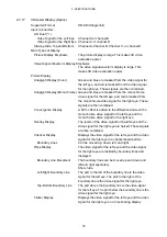
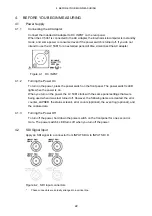
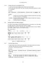
Figure 4-6 SDI output connectors
*
These connectors are actually arranged in a vertical line.
The output signal specifications are shown below.
●
Single input mode (single link) or 3D assist mode (HF SbyS, TOP&BOTM) (option)
The currently selected input signal (channel A or B) is reclocked and transmitted from
OUTPUT SDI A/B. If you select channel C or D, the state of the signal that has been output
up to that point is maintained.
The currently selected input signal (channel C or D) is reclocked and transmitted from
OUTPUT SDI C/D. If you select channel A or B, the state of the signal that has been output
up to that point is maintained.
●
Single input mode (dual link) or simultaneous input mode
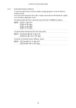
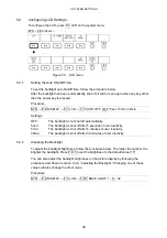
To select the output signal, follow the procedure below.
Procedure
INPUT
→
F•D 1 OUT A/B: A / B
→
F•D 2 OUT C/D: C / D
Settings
A:
The signal applied to INPUT SDI A is reclocked and transmitted from
OUTPUT SDI A/B.
B:
The signal applied to INPUT SDI B is reclocked and transmitted from
OUTPUT SDI A/B.
C:
The signal applied to INPUT SDI C is reclocked and transmitted from
OUTPUT SDI C/D.
D:
The signal applied to INPUT SDI D is reclocked and transmitted from
OUTPUT SDI C/D.


