4. BEFORE YOU BEGIN MEASURING
22
4.
BEFORE YOU BEGIN MEASURING
4.1
Power Supply
4.1.1
Connecting the AC Adapter
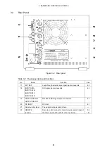
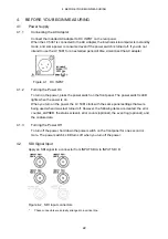
Connect the included AC adapter to DC INPUT on the rear panel.
When the LV 5381 is connected to the AC adapter, the internal microcomputer is in standby
mode, and some power is consumed even if the power switch is turned off. If you do not
intend to use the LV 5381 for an extended period of time, disconnect the AC adapter.
Figure 4-1 DC INPUT
4.1.2
Turning the Power On
To turn on the power, press the power switch on the front panel. The power switch's LED
lights when the power is on.
When you turn on the power, the LV 5381 starts with the same panel settings that were
being used when it was last turned off. However, the following items are cleared: the error
counter, LAPSED, the status screen's error counts (optional), the event log (optional), and
the capture data.
4.1.3
Turning the Power Off
To turn off the power, hold down the power switch on the front panel for one second or
more. The power switch's LED turns off when you turn off the power.
4.2
SDI Signal Input
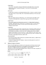
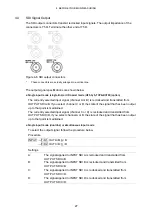
Apply an SDI signal to a connector from INPUT SDI A to INPUT SDI D.
Figure 4-2 SDI input connectors
*
These connectors are actually arranged in a vertical line.

