1. INTRODUCTION
2
1.3
Operating Precautions
1.3.1
Power Supply Voltage
Confirm the voltage of the power source before you connect the power cord to it.
The power requirements of this product are indicated on the rear panel.
Only use a power source that supplies a voltage within the operating voltage range and has
a frequency of 50/60 Hz.
1.3.2
Maximum Allowable Input Voltage
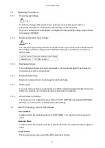
The maximum signal voltage that can be applied to the input connectors is indicated below.
Do not apply excessive voltage to the connectors. Doing so may damage the device or
lead to injury.
Input Connector Maximum Allowable Input Voltage
GENLOCK IN
±
5V (DC+ peak AC)
1.3.3
Mechanical Shock
This instrument contains sensitive components, so it may be damaged if it is dropped or
otherwise exposed to a strong shock.
1.3.4
Electrostatic Damage
Electronic components can be damaged by static discharge.
1.3.5
Warming Up
To ensure more accurate measurements, turn ON the instrument approximately 30 minutes
before you intend to use it to allow its internal temperature to stabilize.
1.3.6
About Power-on Settings
Last memory is not supported (except for the UTILITY SETTING). By setting POWER ON
RECALL, you can start the LT 4600A with preset settings.
1.4
About Terminology Used in this Manual
●
Internal Mode
A state in which the genlock mode is set to INTERNAL. The internal reference signal is
used.
●
Genlock Mode
A state in which the genlock mode is set to STAY-IN-SYNC. An external reference signal is
used.
●
Input Format
The following names are used for the SDI signal input formats.
Summary of Contents for LT 4600A
Page 1: ...LT 4600A MULTIFORMAT VIDEO GENERATOR INSTRUCTION MANUAL MAIN...
Page 83: ...13 SNMP 73 RO Read only R W Read and write...
Page 99: ...14 APPENDIX 89 14 2 MENU TREE The screen shows the initial settings 14 2 1 STATUS MENU...
Page 100: ...14 APPENDIX 90 14 2 2 UTILITY MENU...
Page 101: ...14 APPENDIX 91...
Page 102: ...14 APPENDIX 92 14 2 3 REFERENCE MENU INTERNAL STAY IN SYNC STAY IN SYNC STAY IN SYNC 20...
Page 104: ...14 APPENDIX 94 14 2 5 BLACK MENU 5 1124 4124 NTSC 525i 59 94 PAL 625i 50 63 9814 BLACK1 BLACK1...
Page 107: ...14 APPENDIX 97 GROUP 1 GROUP 1 GROUP 1...
Page 108: ...14 APPENDIX 98 0 256 1 9 1 9 0 1079 0 1919...
Page 109: ...14 APPENDIX 99 SDI 1 100h EB0h 100h EB0h 100h EB0h 100h EB0h 0 1079 INT_1 INT_4 1 99 0 1919...


