background image

IT

ALIANO

POLSKI

ESP
AÑOL

FRANCAIS

DEUTSCH

ENGLISH

7

12

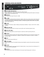
AUX SEND 1-4

Unbalanced mono line outputs with 6.3 mm jack sockets to control an external effects device (POST Fader), or 

an active stage monitor (PRE Fader).

13

INSERT CH1 - CH8

3-pin 6.3 mm jack sockets for inserting an external signal processing device (Compressor, Gate, etc.) in the 

corresponding channels 1 to 8. A special insert cable is required for the connection (Y-cable, 1 x stereo jack to 

2 x mono jack or XLR). The assignment is as follows: TIP = Send, RING = Return, SLEEVE = Masse.

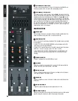
MONO CHANNELS 1 - 16

14

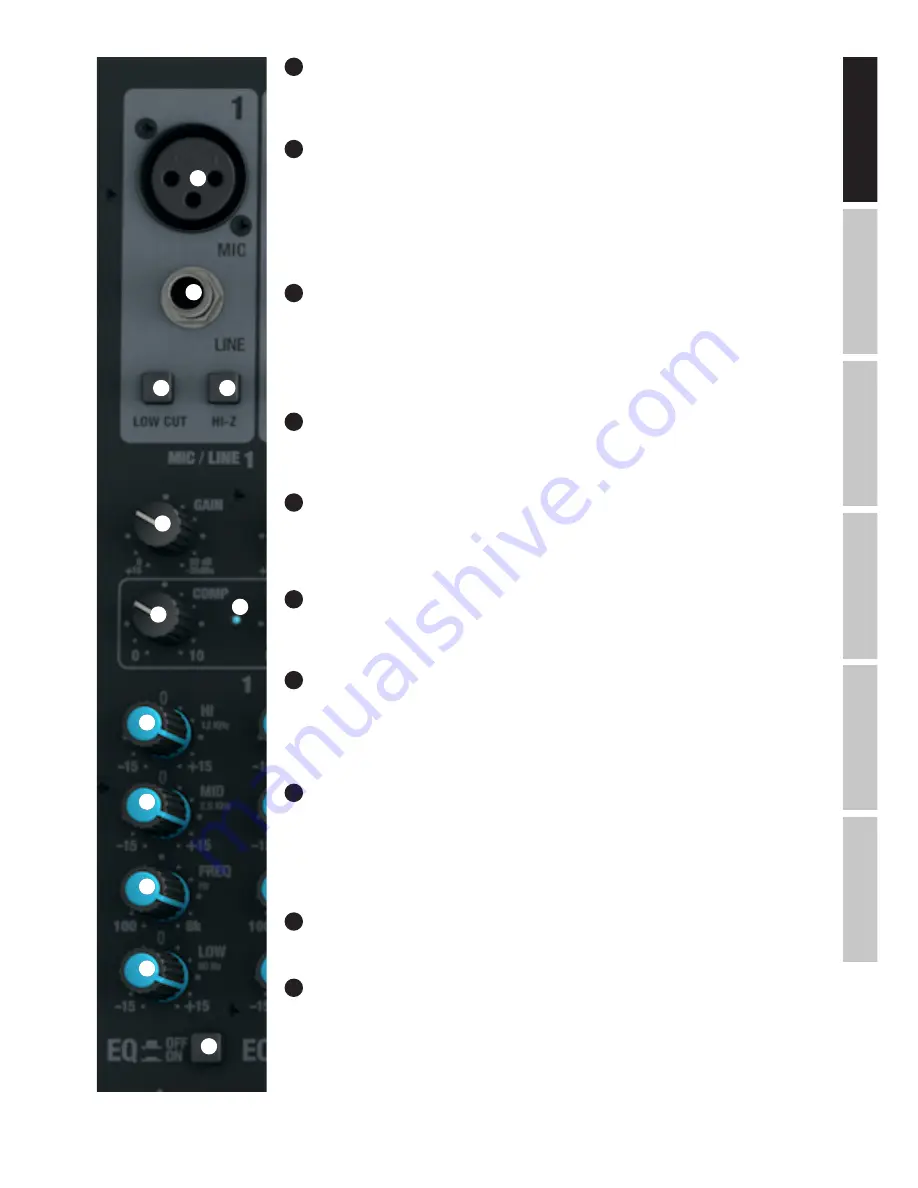
MIC CHANNEL 1-16

Balanced inputs of the channels 1 to 16 with 3-pin XLR sockets for connecting microphones. A 48 V phantom 

power supply is available for operating condenser microphones, and it can be switched centrally to the XLR 

sockets (N° 3). Please set the Gain controller (N  18) to minimum (left stop) before connecting or 

disconnecting a microphone; and switch on the phantom power only after connecting the microphone, or off 

before disconnecting.

15

LINE IN CHANNEL 1-16

Balanced inputs of the mono channels 1 to 16 with 6.3 mm jack to connect a source device with a line level. 

Please set the Gain controller (N  18) to minimum (left stop) before connecting or disconnecting jack cables.

16

LOW CUT CHANNEL 1-16

Low cut filter for suppressing low-frequency signals. Especially with voice and singing transmissions, an 

activated LOW CUT feature (switch in the down position) can reduce disruptive bass frequencies and thus 

increase speech intelligibility. The cut-off frequency is 95 Hz.

17

HI-Z CHANNEL 1-4

Using this pressure switch, the inputs of channels 1 to 4 can be switched separately to high impedance 

(press switch down for activation). Thus, using instrument channels for guitars or basses is possible.

18

GAIN CHANNEL 1-16

Adjusting the gain of the microphone input from 0 to 50 dB, or the sensitivity of the line input from +15 dBu 

to -35 dBu. Adjust the Gain controller so that the Clip LED of the corresponding channel only lights up briefly 

when signal peaks occur. Avoid the permanent lighting of the Clip LED by reducing the input gain or input 

sensitivity.

19

COMP CHANNEL 1-8

Sliding compressor controller for channels 1 to 8. Depending on the setting, the signal is more or less 

compressed, i.e., the dynamics of the signal is restricted (controller to the left stop = compressor is disabled, 

controller to the right stop = maximum compression). The level loss caused by the increasingly stronger 

compression is automatically compensated by the compressor unit. The use of the compressor can provide 

for an improved clarity of a singing voice in the mix.

20

COMP LED

As soon as the compressor is active, the display LED lights up.

21

EQUALIZER HI CHANNEL 1-16

Equalizer high band for channels 1 to 16 (12 kHz, +/-15 dB). When turned to the left, levels are lowered, when 

turned to the right, they are raised. In the centre position (resting point), the equalizer is inactive.

14

15

16

17

18

19

21

22

23

24

25

20

Summary of Contents for LDVIBZ24DC

Page 1: ...USER S MANUAL BEDIENUNGSANLEITUNG MANUEL D UTILISATION MANUAL DE USUARIO INSTRUKCJA OBS UGI MANUALE D USO VIBZ 24DC 24 CHANNEL MIXING CONSOLE WITH DFX AND COMPRESSOR LDVIBZ24DC...

Page 2: ...53 CARACT RISTIQUES TECHNIQUES 53 55 DECLARATIONS 55 ESPA OL MEDIDAS DE SEGURIDAD 56 57 INTRODUCCI N 57 GU A R PIDA DE CABLEADO 58 CONEXIONES CONTROLES E INDICADORES 59 69 CANALES MONO 1 16 60 62 CANA...

Page 3: ...ped with an earthing contact then it must be connected to an outlet with a protective ground Never deactivate the protective ground of a power cord 23 If the equipment has been exposed to strong fluct...

Page 4: ...r this reason avoid prolonged exposure to volumes in excess of 90 dB CAUTION IMPORTANT INFORMATION ABOUT LIGHTING PRODUCTS 1 The product has been developed for professional use in the field of event t...

Page 5: ...at the Clip LED of the corresponding channel only lights up briefly when signal peaks occur Avoid the permanent lighting of the Clip LED by reducing the input gain Gain 6 Press the L R switch of the c...

Page 6: ...rating system Windows XP Windows 10 MAC OS X USB 2 0 recording and playback 5 MAIN MIX OUTPUT BAL Balanced stereo line output with 3 pin XLR jack sockets to connect an active PA system Output of the m...

Page 7: ...ed LOW CUT feature switch in the down position can reduce disruptive bass frequencies and thus increase speech intelligibility The cut off frequency is 95 Hz 17 HI Z CHANNEL 1 4 Using this pressure sw...

Page 8: ...erefore dependent on the latter To control a stage monitor bring the switch to the up position PRE The signal is picked up before the channel volume controller N 32 and the volume of the stage monitor...

Page 9: ...the corresponding channel to the channel group 3 PAN all the way to the left to the channel group 4 PAN all the way to the right or to both groups of channel groups 3 and 4 in the same proportion PAN...

Page 10: ...f the Clip LED by reducing the input gain or input sensitivity if necessary reduce the volume of the external audio device 42 EQUALIZER HI CHANNEL 17 18 AND 19 20 Equalizer high band for channels 17 1...

Page 11: ...of the corresponding channel and downwards to decrease it 54 SIGNAL LED CHANNEL 17 18 AND 19 20 The signal LED lights up as soon as an audio signal is present at the corresponding channel depending on...

Page 12: ...d as the signal source in the down position the USB interface on the rear side of the mixer is selected 63 EQUALIZER HI CHANNEL 21 22 AND 23 24 Equalizer high band for channels 21 22 and 23 24 12 kHz...

Page 13: ...22 AND 23 24 The signal LED lights up as soon as an audio signal is present at the corresponding channel depending on the input level and setting of the gain or input sensitivity GAIN 76 CLIP LED CHAN...

Page 14: ...jack socket for connecting a headphone This connection allows you to listen to various signals A Switch N 100 CTRL ROOM SOURCE MAIN GR is not pressed down and no PFL switch is depressed Sum signal MAI...

Page 15: ...me controller for adding the effects signal of the internal effects device to the MAIN MIX sum channel 98 OUTPUT LEVEL 2x 12 segment LED level display for visualising the level in the MAIN MIX stereo...

Page 16: ...troller for the stereo line outputs MAIN MIX OUTPUT N 5 and N 6 Push the Fader button upwards to increase the volume and downwards to decrease it Before you turn on the power of the connected PA syste...

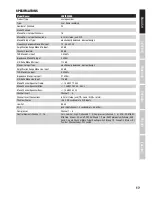
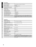
Page 17: ...sign Amplification Range Mono Line Input 50 dB THD Mono Line Input 0 0045 Impedance Mono Line Input 21 kOhm S N Ratio Mono Line Input 116 dB Mono Channel Equalizer Treble 15 dB 12 kHz Mono Channel Equ...

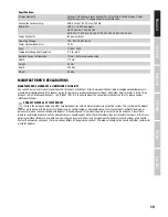
Page 18: ...Mute Fader Routing switch Group 1 2 Group 3 4 Main L R Bal Channel Fader PFL switch Master Section AUX Effect Send Channels 4 AUX Effect Send Connections 4 x 6 3 mm stereo jack unbalanced Balanced Ste...

Page 19: ...s pdf To request warranty service for a product please contact Adam Hall GmbH Daimler Stra e 9 61267 Neu Anspach Email Info adamhall com 49 0 6081 9419 0 To enquire about the current declaration of co...

Page 20: ...wenden Sie zur Reinigung des Ger ts ein trockenes Tuch 20 Beachten Sie alle in Ihrem Land geltenden Entsorgungsgesetze Trennen Sie bei der Entsorgung der Verpackung bitte Kunststoff und Papier bzw Kar...

Page 21: ...sik en hinzuweisen Geh rsch den durch hohe Lautst rken und Dauerbelastung Bei der Verwendung dieses Produkts k nnen hohe Schalldruckpegel SPL erzeugt werden die bei K nstlern Mitarbeitern und Zuschaue...

Page 22: ...r bei Pegelspitzen des anliegenden Signals kurz aufleuchtet Vermeiden Sie permanentes Leuchten der Clip LED durch Reduzieren der Eingangsvorverst rkung Gain 6 Bringen Sie den Schalter L R der verwende...

Page 23: ...Mikrofonkan le auf Minimum 4 USB IN OUT USB B Anschlussbuchse zum Verbinden mit einem Computer mit Windows oder MAC Betriebssystem Windows XP Windows 10 MAC OS X USB 2 0 Recording und Playback 4 USB I...

Page 24: ...Beschallungsanlagen etc Ausgabe der Gruppen Signale 1 bis 4 des Mischpults 12 AUX SEND 1 4 Unsymmetrische Mono Line Ausg nge mit 6 3mm Klinkenbuchsen zum Ansteuern externer Effektger te POST Fader ode...

Page 25: ...n 15 bis 35 dBu Stellen Sie den Gain Regler so ein dass die Clip LED des entsprechenden Kanals nur bei Pegelspitzen des anliegenden Signals kurz aufleuchtet Vermeiden Sie permanentes Leuchten der Clip...

Page 26: ...as interne digitale Effektger t Effekt Send Post Fader Verwenden Sie den Line Ausgang AUX SEND 4 Nr 12 zur Ansteuerung eines externen Effektger ts Bei der Verwendung der AUX SEND 4 Klinkenbuchse wird...

Page 27: ...werden die Signale der in eine Gruppe zusammengefassten Kan le auf die entsprechenden Line Ausg nge GROUP OUT 3 4 geroutet Die Gesamtlautst rke der so gebildeten Gruppe wird mit Hilfe des Pegelstelle...

Page 28: ...astpunkt ist der Equalizer inaktiv 43 EQUALIZER MID HI KANAL 17 18 19 20 Equalizer Mittenband HI f r die Kan le 17 18 und 19 20 3kHz 15 dB Nach links gedreht werden die hohen Mitten abgesenkt nach rec...

Page 29: ...Eingangsempfindlichkeit GAIN 55 CLIP LED KANAL 17 18 19 20 Sobald die rote Clip LED aufleuchtet wird der Eingang des entsprechenden Kanals an der Verzerrungs grenze betrieben Stellen Sie den Gain Regl...

Page 30: ...1 22 Umschalten der Signal Quelle f r den Stereo Kanal 21 22 In nicht heruntergedr ckter Position sind die Cinch Buchsen als Signal Quelle aktiviert in heruntergedr ckter Position die USB Schnittstell...

Page 31: ...henden Kanals in die heruntergedr ckte Position Gleichzeitig beginnt die MUTE LED des Schalters zu leuchten Beim Deaktivieren der Stummschaltung erlischt die MUTE LED 74 FADER KANAL 21 22 23 24 Pegels...

Page 32: ...Um einen Eingangskanal Kanal 21 22 und 23 24 direkt auf den Summen Kanal MAIN MIX zu routen bringen Sie den Schalter L R des entsprechenden Kanals in die heruntergedr ckte Position 80 PFL KANAL 21 22...

Page 33: ...alter zum Ein und Ausschalten des Summen Equalizers Nr 83 In heruntergedr ckter Position ist der Equalizer aktiviert in nicht heruntergedr ckter Position deaktiviert 85 ANZEIGE LED 48V Sobald die Phan...

Page 34: ...eige angezeigt wird sobald der PFL Schalter des entsprechenden Kanals gedr ckt wird Um Verzerrungen zu vermeiden reduzieren Sie den Ausgangspegel am Pegelsteller MAIN MIX Nr 110 bzw reduzieren Sie den...

Page 35: ...ie vor dem Einschalten der angeschlossenen Beschallungsanlage den Pegelsteller auf Minimum 111 MAIN MIX MUTE Bringen Sie den Schalter in die heruntergedr ckte Position um den Summen Kanal MAIN MIX stu...

Page 36: ...bau Verst rkungsbereich Mono Line Eingang 50dB THD Mono Line Eingang 0 0045 Impedanz Mono Line Eingang 21k Ohm S N Ratio Mono Line Eingang 116dB Mono Kanal Equalizer H hen 15dB 12kHz Mono Kanal Equali...

Page 37: ...tch Group 1 2 Group 3 4 Main L R Bal Kanal Fader PFL switch Master Sektion AUX Effekt Send Kan le 4 AUX Effekt Send Anschl sse 4x 6 3 mm Stereoklinke Unbalanced Symmetrische Stereo Main Ausg nge 2 Sym...

Page 38: ...anderen Abf llen und f hren es zur F rderung nachhaltiger Wirtschaftskreisl ufe dem Recycling zu Als Privatkunde erhalten Sie Informationen zu umweltfreundlichen Entsorgungsm glichkeiten ber den H ndl...

Page 39: ...sa prise secteur s il s agit d un appareil aliment Cet appareil ne doit tre r par que par un personnel autoris 19 Pour le nettoyage de l appareil utilisez un chiffon sec 20 Observez toutes les r gleme...

Page 40: ...de cet appareil est soumise aux r glementations et directives en vigueur dans votre pays en mati re de pr vention d accident En tant que fabricant Adam Hall est tenu de vous avertir formellement des r...

Page 41: ...la LED Clip de la voie ne s allume qu occasionnellement sur les cr tes de signal Si la LED Clip s allume de fa on continue r duisez le gain sur le pr ampli d entr e 6 Placez la touche L R des voies u...

Page 42: ...Windows 10 macOS USB 2 0 en enregistrement et en lecture 5 SORTIE MAIN MIX BAL Sortie st r o sym trique au niveau ligne sur connecteurs XLR 3 points pour connexion d un syst me de sonorisation actif...

Page 43: ...dio au niveau ligne Avant de brancher d brancher le c ble jack veuillez r gler le potentiom tre Gain n 18 au minimum en le tournant fond gauche 16 FILTRE LOW CUT VOIES 1 16 Filtre passe haut att nuant...

Page 44: ...e AUX SEND 1 et 2 n 12 27 AUX 1 AUX 2 PRE POST VOIES 1 16 Si vous d sirez utiliser le d part AUX 1 ou 2 pour alimenter un multieffet externe le s lecteur doit se trouver en position POST touche enfonc...

Page 45: ...n 104 si vous d sirez affecter le signal audio des groupes aux g n raux MAIN MIX appuyez sur la touche L R n 105 36 GR 3 4 VOIES 1 16 La touche GR 3 4 permet d assigner le signal de la voie aux groupe...

Page 46: ...voies 1718 et 19 20 fr quence centrale 3 kHz 15 dB Tourner vers la gauche pour baisser les haut m diums vers la droite pour les monter En position centrale crant e le correcteur est inactif 44 GALISE...

Page 47: ...17 18 19 20 D s que la LED rouge Clip s allume c est que l entr e de la voie approche la limite de la distorsion R glez le potentiom tre Gain n 41 de fa on ce que la LED Clip ne clignote qu occasionn...

Page 48: ...EUR HI VOIES 21 22 23 24 galiseur d aigus pour les voies 21 22 ou 23 24 fr quence centrale 12 kHz 15 dB Tourner vers la gauche pour baisser les aigus vers la droite pour les monter En position central...

Page 49: ...appuyez sur sa touche MUTE position enfonc e L indica teur LED MUTE de la voie s allume alors Appuyez de nouveau sur la touche MUTE pour d sactiver la fonction Mute l indicateur LED MUTE s teint 74 FA...

Page 50: ...lis sur le vum tre 12 LED des g n raux MAIN MIX Lorsque vous enfoncez la touche PFL d une voie son indicateur LED PFL s allume ainsi que celui situ sous le vum tre des g n raux MAIN MIX D s que la tou...

Page 51: ...otentiom tre permet de r gler le niveau global du bus DFX AUX2 recueillant les signaux pr lev s sur chacune des voies 1 23 2 via le potentiom tre DFX AUX2 93 AUX SEND 3 Potentiom tre de r glage de niv...

Page 52: ...nsion de la sonorisation connect e r glez le volume au minimum fader baiss 105 GROUP 1 2 L R Touche d assignation du signal des groupes GROUP 1 2 aux g n raux MAIN MIX 106 GROUP 3 4 R glage de volume...

Page 53: ...de s lectionner la console USB Audio CODEC en tant que p riph rique d enregistrement et de lecture dans le tableau de bord Son Pr f rences Syst me Son CARACT RISTIQUES TECHNIQUES R f rence Mod le LDV...

Page 54: ...pes 1 2 Groupes 3 4 g n raux Main L R Bal fader de voie touche PFL Section Master Nombre de D parts AUX Effet 4 Connecteurs D part AUX Effet 4 x jacks 6 35 mm 3 points c bl s en asym trique Sortie St...

Page 55: ...s r parations veuillez contacter Adam Hall GmbH Daimlerstra e 9 61267 Neu Anspach E Mail Info adamhall com 49 0 6081 9419 0 Vous pouvez nous demander la d claration de conformit actuel le l adresse in...

Page 56: ...alg n desperfecto apague inmediatamente el equipo y desenchufe el cable el ctrico si se trata de un equipo activo nicamente un t cnico especialista debe reparar el equipo 19 Para limpiar el equipo ut...

Page 57: ...un uso profesional Por consiguiente si se aplica a un uso comercial estar sujeto a las normas y reglamentos de la Asociaci n para la prevenci n de accidentes de su sector profesional Como fabricante...

Page 58: ...trol de ganancia de los canales de tal forma que el LED CLIP del canal correspondiente solo se ilumine brevemente en los picos de la se al entrante Para que el LED CLIP no est encendido de forma fija...

Page 59: ...ws XP Windows 10 Mac OS X con conector USB 2 0 para grabaci n y reproducci n 5 MAIN MIX OUTPUT BAL Salida de l nea est reo balanceada con XLR de 3 pines para conectar a un sistema de refuerzo sonoro T...

Page 60: ...ecuencia y as mejorar la inteligibilidad La frecuencia de corte es 95 Hz 17 HI Z CANALES 1 4 Al pulsar este bot n los jacks de entrada de los canales 1 a 4 CH1 pasan a alta impedancia Esto permite emp...

Page 61: ...sador de efectos externo env o de efecto postfader Use la salida de l nea AUX SEND 3 12 para enviar la se al 29 NIVEL DFX AUX 4 POST CANALES 1 16 Control para mezclar la se al de los canales 1 a 16 co...

Page 62: ...a se al a los grupos 3 y 4 a la vez PAN en la posici n intermedia Adem s se env a la se al de un grupo de canales a la salida de l nea GROUP OUT 3 4 El nivel global de los grupos se ajusta mediante el...

Page 63: ...ales 17 18 y 19 20 12 kHz 15 dB Girar a la izquierda para disminuir los agudos y a la derecha para realzarlos En la posici n central de reposo el control est inactivo 42 ECUALIZADOR HI CANALES 17 18 1...

Page 64: ...Deslice el fader hacia arriba para aumentar el nivel del canal y hacia abajo para disminuirlo 54 LED DE SE AL CANALES 17 18 19 20 El LED se ilumina si hay se al de audio en la entrada del canal depend...

Page 65: ...ente de se al mientras que en la posici n pulsada se selecciona el puerto USB del panel posterior de la mesa de mezclas 63 ECUALIZADOR HI CANALES 21 22 23 24 Control de agudos de los canales 21 22 y 2...

Page 66: ...ra aumentar el nivel del canal y hacia abajo para disminuirlo 75 LED DE SE AL CANALES 21 22 23 24 El LED se ilumina si hay se al de audio en la entrada del canal depende del nivel de entrada y de la p...

Page 67: ...ck est reo de 6 3 mm para conectar los auriculares En este conector se pueden monitorar varias se ales A Bot n 100 CTRL ROOM SOURCE MAIN GR sin pulsar y bot n PFL sin pulsar se al de mezcla MAIN MIX B...

Page 68: ...Control de nivel para mezclar la se al de efecto del procesador interno de efectos con el canal de mezcla MAIN MIX 98 OUTPUT LEVEL Doble v metro LED de 12 segmentos que muestra el nivel del canal est...

Page 69: ...rupos GROUP 3 4 con el canal de mezcla MAIN MIX Antes de encender el sistema de refuerzo sonoro que haya conectado sit e este fader al m nimo 107 L R GROUP 3 4 Bot n para enviar la se al de grupos GRO...

Page 70: ...Sonido Preferencias del sistema Sonido como un dispositivo de entrada o salida CARACTER STICAS T CNICAS Nombre del modelo LDVIBZ24DC Tipo de producto Mesa de mezclas anal gica Tipo Grabaci n en direct...

Page 71: ...nv o de fader Group 1 2 Group 3 4 Main L R Bal fader de canales bot n PFL Secci n master Canales de env o de efecto AUX 4 Conectores de env o de efecto AUX 4 jacks est reo de 6 3 mm no balanceado Sali...

Page 72: ...cio t cnico p ngase en contacto con Adam Hall GmbH Daimlerstra e 9 61267 Neu Anspach Alemania correo electr nico Info adamhall com 49 0 6081 9419 0 Puede solicitar la declaraci n de conformidad envian...

Page 73: ...e li urz dzenie zosta o uszkodzone w inny spos b nale y je natychmiast wy czy i od czy od gniazda sieciowego je li urz dzenie jest aktywne Napraw takiego urz dzenia mo e wykona tylko autoryzowany pers...

Page 74: ...roducent zobowi zana do wyra nego informowania o potencjalnym zagro eniu dla zdrowia Utrata s uchu w wyniku wysokiego poziomu g o no ci i d ugotrwa ego nara enia po dczas stosowania tego produktu mo e...

Page 75: ...szczytowej Clip odpowiedniego kana u zapala a si na kr tko wy cznie dla szczytowych poziom w przekazywanego sygna u Unika ci g ego wiecenia si diody warto ci szczytowej poprzez obni enie wst pnego wz...

Page 76: ...ows lub MAC Windows XP Windows 10 MAC OS X USB 2 0 nagrywanie i playback 5 MAIN MIX OUTPUT BAL Symetryczne stereofoniczne wyj cie liniowe wyposa one w 3 stykowe gniazda XLR do pod czenia aktywnego sys...

Page 77: ...ej ciowych o liniowym poziomie sygna u Przed pod czeniem od czeniem kabla zako czonego z czem jack 6 3 mm nale y ustawi regulator wzmocnienia nr 18 na minimum maksymalny obr t w lewo 16 LOW CUT KANAL...

Page 78: ...RE Skorzysta z wyj liniowych AUX SEND 1 i 2 nr 12 w celu wyprowadze nia sygna u 27 AUX 1 AUX 2 PRE POST KANAL 1 16 Je eli sygna wyprowadzany jest do zewn trznego efektu za pomoc wyj cia AUX 1 lub AUX...

Page 79: ...dnie wyj cia liniowe GROUP OUT 1 2 G o no ca kowit utworzonej w ten spos b grupy mo na regulowa za pomoc regulatora g o no ci GROUP 1 2 nr 104 Je eli sygna y audio maj by przetrasowywane na sum kana w...

Page 80: ...nienia wej cia lub czu o ci wej cia ew zmniejszy g o no pod czonego urz dzenia 42 EQUALIZER HI KANAL 17 18 19 20 Korektor d wi ku ton w wysokich kana w 17 18 oraz 19 20 12 kHz 15 dB Obr t w lewo powod...

Page 81: ...j regulatora panoramy 52 MUTE KANAL 17 18 19 20 W celu wyciszenia danego kana u nale y upewni si e przycisk wyciszania MUTE odpowiedniego kana u znajduje si we wci ni tej pozycji Po naci ni ciu przyci...

Page 82: ...PFL odpo wiedniego kana u i dioda LED PFL w ramach wska nika poziomu sumy kana w MAIN MIX Po ponownym naci ni ciu przycisku PFL pozycja wyj ciowa diody LED PFL zgasn KANA Y STEREO 21 22 I 23 24 60 LIN...

Page 83: ...ziomu kana u nr 74 w zwi zku z czym g o no monitora scenicznego mo e zosta ustawiona niezale nie od g o no ci kana u 70 AUX 3 POST KANAL 21 22 23 24 Regulator poziomu sygna u s u cy do dodawania sygna...

Page 84: ...o ci GROUP 3 4 nr 106 Je eli sygna y audio maj by przetrasowywane na sum kana w MAIN MIX nale y nacisn przycisk L R nr 107 pozycja wci ni ta 79 L R KANAL 21 22 23 24 W celu przetrasowania kana u wej c...

Page 85: ...0 DFX PEAK LED Gdy zapali si czerwona dioda warto ci szczytowej efekt w DFX oznacza to e wej cie wewn trznego efektu pracuje na granicy zniekszta ce Ustawi regulator poziomu wysy ki sygna u do efektu...

Page 86: ...wci ni ty GR3 4 102 CTRL ROOM LEVEL Regulator poziomu stereofonicznego wyj cia liniowego CTRL ROOM nr 10 Przed w czeniem pod czonego monitora ods uchowego nale y ustawi regulator poziomu na minimum 10...

Page 87: ...ja w systemach operacyjnych Apple Mac OS X 10 5 lub nowszy Instalacja nie wymaga pobierania sterownik w z Internetu ani stosowania sterownik w znajduj cych si na zewn trznych no nikach pami ci Pulpit...

Page 88: ...nanie niezale ne Zakres wzmocnienia monofonicznego wej cia liniowego 50 dB THD monofonicznego wej cia liniowego 0 0045 Impedancja monofonicznego wej cia liniowego 21 k SNR monofonicznego wej cia linio...

Page 89: ...AUX Send 3 4 post Channel Mute Fader Routing switch Group 1 2 Group 3 4 Main L R Bal Kanal Fader PFL switch Sekcja Master Kana y AUX Send wysy ka do efektu 4 Z cza AUX Send wysy ka do efektu 4 x nies...

Page 90: ...y utylizowa oddzielnie od innych odpad w i przekaza do punktu recyklingu w celu ponownego wykorzystania u ytych w nim materia w w ramach idei zr wnowa onego rozwoju Klienci prywatni otrzymuj informacj...

Page 91: ...Per la pulizia del dispositivo utilizzare un panno pulito 20 Rispettare le leggi sullo smaltimento in vigore nel Paese di installazione Al momento di smaltire l imballo separare la plastica dalla car...

Page 92: ...li rischi per la salute Danni all udito provocati da un esposizione prolungata a un livello sonoro elevato l utilizzo di questo prodotto pu generare elevati livelli di pressione sonora SPL che possono...

Page 93: ...ispondente si accenda brevemente solo se il segnale presente raggiunge picchi di livello Per evitare che il LED CLIP rimanga acceso ridurre la preamplificazione d ingresso GAIN 6 Lasciare premuto l in...

Page 94: ...ione e riproduzione USB 2 0 5 MAIN MIX OUTPUT BAL Uscita di linea stereo bilanciata con XLR a 3 poli per il collegamento di un impianto di diffusione acustica Uscita del segnale di missaggio del mixer...

Page 95: ...i Soprattutto durante la trasmissione di voce e canto attivando la funzione LOW CUT interruttore premuto si possono ridurre le basse frequenze indesiderate e aumentare cos l intelligibilit del testo L...

Page 96: ...interruttore in posizione PRE non premuto Il segnale verr ora misurato prima del fader del canale 32 e il volume del monitor da palcoscenico potr essere regolato indipendentemente dal livello del cana...

Page 97: ...il canale corrispondente al gruppo di canali 3 PAN tutto a sinistra al gruppo canali 4 PAN tutto a destra o con lo stesso segnale per i due gruppi di canali 3 e 4 PAN al centro Nel contempo i segnali...

Page 98: ...n posizione intermedia si sente un clic l equalizzatore disattivato 43 EQ MID HI CANALI 17 18 E 19 20 EQ MID HI CANALI 17 18 E 19 20 3 kHz 15 dB Ruotare a sinistra per abbassare i medi alti e a destra...

Page 99: ...sibilit d ingresso GAIN 55 LED CLIP CANALI 17 18 E 19 20 Se il LED CLIP si accende in rosso l ingresso del canale corrispondente funziona al limite di distorsione Posizionare il regolatore di guadagno...

Page 100: ...ti e a destra per alzarli In posizione intermedia si sente un clic l equalizzatore disattivato 64 EQ MID HI CANALI 21 22 E 23 24 Equalizzatore dei medi HIGH per i canali 21 22 e 23 24 3 kHz 15 dB Ruot...

Page 101: ...corrispondente funziona al limite di distorsione Posizionare il regolatore di guadagno 61 in modo che il LED CLIP si accenda brevemente solo se il segnale presente raggiunge picchi di livello Per evit...

Page 102: ...i intercettare a scelta diversi segnali A Interruttore 100 CTRL ROOM SOURCE MAIN GR non premuto e nessun interruttore PFL premuto segnale di missaggio MAIN MIX B Interruttore 100 premuto e nessun inte...

Page 103: ...i livello LED a 12 segmenti per visualizzare il livello nel canale di missaggio stereo MAIN MIX e per effettuare un impostazione del guadagno pi precisa poich il livello di un segnale d ingresso indic...

Page 104: ...rruttore per l instradamento dei segnali di gruppo GROUP 3 4 sul canale di missaggio MAIN MIX premuto 108 MUTE GROUP 1 2 Per silenziale il segnale dei gruppi GROUP 1 2 lasciare l interruttore premuto...

Page 105: ...input e output DATI TECNICI Nome del modello LDVIBZ24DC Tipo di prodotto Mixer analogico Tipo Registrazione live home Numero di canali 24 Canali mono Canali d ingresso mono di microfono linea 16 Conne...

Page 106: ...t silenziamento canali interruttore instradamento fader Group 1 2 Group 3 4 Main L R Bal fader canale interruttore PFL Sezione Master Canali di invio effetti AUX 4 Connessioni di invio effetti AUX 4 j...

Page 107: ...ations pdf In caso di assistenza rivolgersi a Adam Hall GmbH Daimlerstra e 9 61267 Neu Anspach E mail Info adamhall com 49 0 6081 9419 0 La dichiarazione di conformit aggiornata pu essere richiesta a...

Page 108: ...WWW LD SYSTEMS COM Adam Hall GmbH Daimlerstrasse 9 61267 Neu Anspach Germany Tel 49 0 6081 9419 0 Fax 49 0 6081 9419 1000 web www adamhall com e mail mail adamhall com REV 04...

Reviews: