background image

6

DSC Control Software

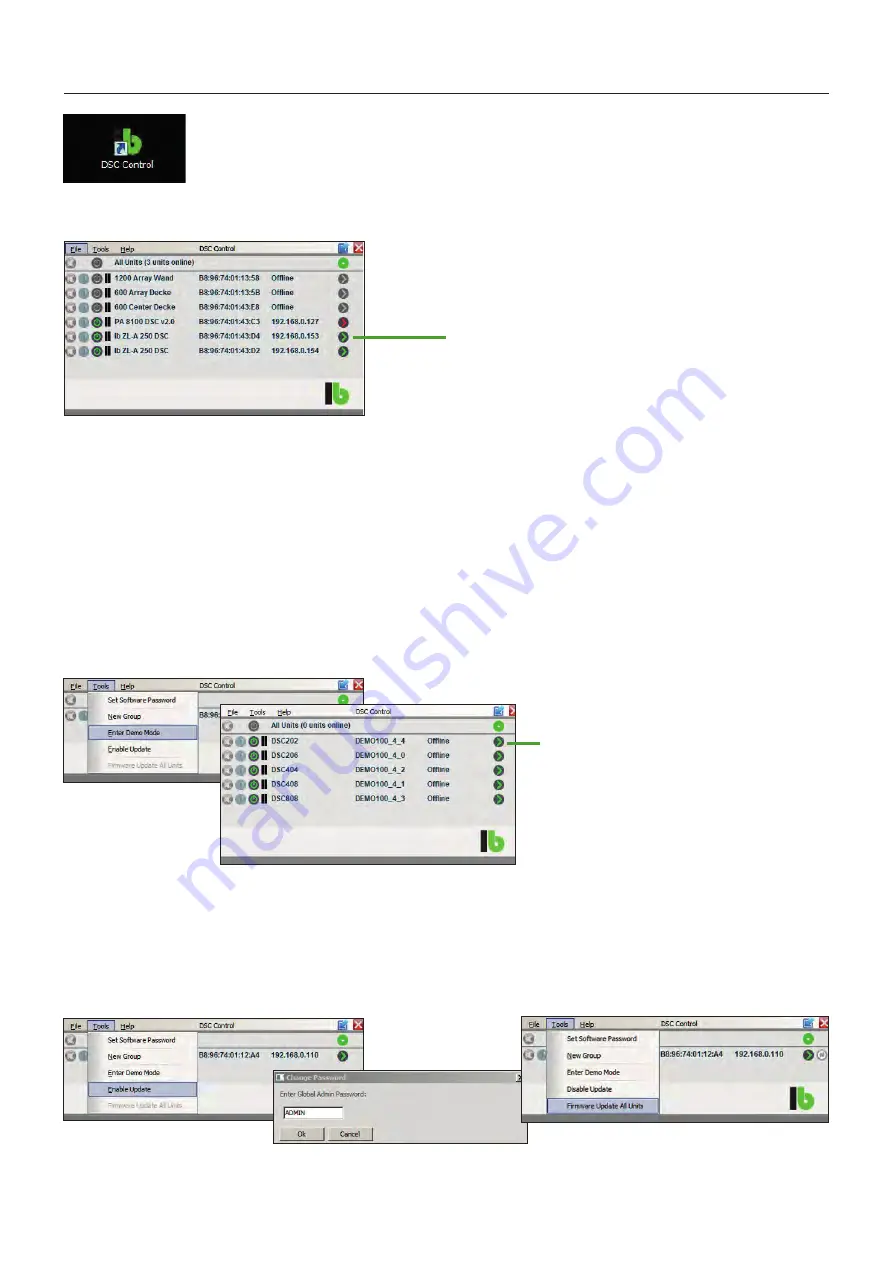
Clicking on a button with a green arrow on the right side opens
the window of the corresponding device. In that window
changes of the DSP settings can be made. The arrow of the
opened device turns red. (Shown for PA 8100 DSC v2.0)

If there is no hardware connected, the „Demo Mode“ provides virtual implementations of one of our five DSC models. Select 
„Tools”and “Enter Demo Mode”. (2 × IN/2 × OUT, 2 × IN/6 × OUT, 4 × IN/4 × OUT, 4 × IN/8 × OUT und 8 × IN/8 × OUT). All amplifiers 
of the PA S-DSC series are equipped with an 2×2 DSP (2 × IN and 2 × OUT). (DSC 202).

In the virtual demo devices all settings can be made and saved as presets. The „Demo Mode“ will be activated via „Tools“ and 
„Enter Demo Mode“. All demo devices can be opened by clicking on the green arrow. 

Firmware Update

Bevor updating the Firmware, save all passwords and presets. Installing a new firmware can be made also in the overview window. 
For firmware updates select „Tools“ and then „Enable Update“. Enter the admin or developer password and select „Firmware Update 
all Units“, then all connected devices will be updated. This process can take a few minutes.

Network-Scan

Demo Mode

Starting the DSC Control software first
opens the network scan window.

Clicking on a button with a green arrow
on the right side opens the window of the
corresponding demo device.

Summary of Contents for PA 2100 S-DSC

Page 1: ...rix the DSP also o ers ten fully parametric filters a delay of up to 10 ms compressors and limiters for each input and output Up to 100 presets can be stored permanently We can also preconfigure proje...

Page 2: ...tent Important Safety Informations 3 Technical Data General 4 Technical Data Model Specific 4 Front Controls 5 Backside Controls 5 DSC Control Software 6 Network Instructions to control DSPs 11 Extern...

Page 3: ...adiators or other heat sources Upon sudden change of climatic conditions e g transfer from a cold place to a warm room water may condense inside the device which may lead to malfunction or damage Befo...

Page 4: ...er DIP switch Controls Power switch dual LED SLEEP ON at front DIP switches at back Auto ON Steady ON Ground Lift Additional connectors VCA inputs 0 10 V for each channel also for DV modules ON Stand...

Page 5: ...e channel pair is active permanently STEADY ON MODE dip switch 2 GROUND LIFT In the LIFT position up audio inputs and outputs are groun ded softly In the GROUND position down audio ground is connected...

Page 6: ...he virtual demo devices all settings can be made and saved as presets The Demo Mode will be activated via Tools and Enter Demo Mode All demo devices can be opened by clicking on the green arrow Firmwa...

Page 7: ...ted limiter value Channel labels Channels can be linked in pairs Link The settings of the first channel besi de the output mixer setting are then copied to the second channel Save and load presets on...

Page 8: ...s HPF and Low pass LPF filters Parametric filters Bell Notch All Pass Low Shelf High Shelf Band Pass High Pass Low Pass Output mixer For each output all inputs can be mixed at will Output Channel Outp...

Page 9: ...s also able to change the default passwords for all levels and replace them by custom ones as well as perform firmware updates Default Password DEVELOP Development Mode Change Passwords In the Develop...

Page 10: ...min or Develop ment Mode can be entered Enter Password The interlock is hereby repealed In the Development Mode the menu shows the additional tab Preset Here you can change preset related access right...

Page 11: ...e and connect with the device Open tab Hardware Configure Network Settings and activate the Telnet Interface A fixed IP address can be assigned as well The device is accessed via its IP address on TCP...

Page 12: ...cts The control range from 0 to 80 dB is divided into 64 steps and the current level is stored automatically at power cycle Multi Channel Volume Control using DV module The DV modules are also able to...

Page 13: ...allow for the ON MUTE functionality Several amplifier channels can be controlled in parallel using the 0 10 V outputs of dimmer actuators or smart home controllers Proceed as for the analogue volume c...

Page 14: ...UT 1 sym INPUT 2 sym 0 0 AUTO STEADY ON switchable GROUND LIFT back Gain Filters Delay Limiter Compressor 2 2 Mixer Matrix Gain Filters Delay Limiter Compressor DSP Gain Filters Delay Limiter Compress...

Page 15: ...l Drawings PA S DSC Series Technical Drawings WP V RP V RP 1 U DV Module WP V RP V RP 1U DV Module 110 43 Dimensions PA 2100 S DSC rear front 110 242 130 87 5 sides front mounting bracket below on top...

Page 16: ...ges without prior notice lb Lautsprecher und Beschallungstechnik GmbH info lb lautsprecher de www lb lautsprecher de Steinerstr 15 K 81369 M nchen Tel 49 89 1893109 0 Fax 29 lb Lautsprecher und Bescha...

Reviews: