


The Rear Panel
5
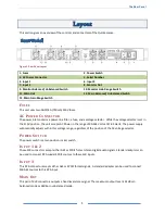
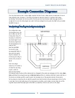
Layout
This section gives an overview of the controls and connectors of the Quintessence.
Figure 1- Rear Panel Layout
1. Fuses
2. Power Switch
3. AC Power Connector
4. Serial Number
5. Input 1
6. Input 2
7. Input 3
8. Monitor Out
9. Monitor Balanced/ Unbalanced Switch
10. Monitor Gain Range Switch
11. Main Out
12. Main Balanced/ Unbalanced Switch
13. Main Gain Range Switch
F
USES
This unit uses two AGC3/4A (750mA) 250V fuses.
AC
P
OWER
C
ONNECTOR
The power inlet contains a power-line filter, a fuse, and a voltage selector. While the voltage selector is set in
the 115V position, the unit accepts AC Power in the range of 90-264 Volts at 47-63 Hertz. The power supply
automatically adjusts within this voltage range, regardless of the position of the AC voltage selector.
P
OWER
S
WITCH
The power switch is a two position rocker switch.
I
NPUT
1
&
2
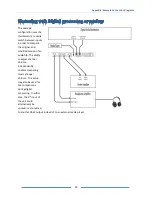
These XLR connectors accept either AES or SPDIF format stereo digital audio signals. Standard adapters can
be used to connect RCA coaxial SPDIF sources to these XLR inputs.
I
NPUT
3
This RCA connector accepts either AES or SPDIF format signals. A standard adapter can be used to connect
XLR AES sources to this RCA input.
M
AIN
O
UT
This pair of XLR connectors outputs a fixed level stereo signal. The maximum output level is 24dBu in
balanced mode or 18dBu in unbalanced mode.


