


LAUNCH X-431 Russia GAZ Diagnosis
7
Figure 21
ADC Channels
Note: ECU uses A/D converter channels for
several sensors, i.e. oil temperature sensor
and so on. Here, ADC refers to the Analog
Digital Converter.
Click [ADC CHANNELS] in the function menu.
X-431 will display the data stream items as
shown in Figure 22.
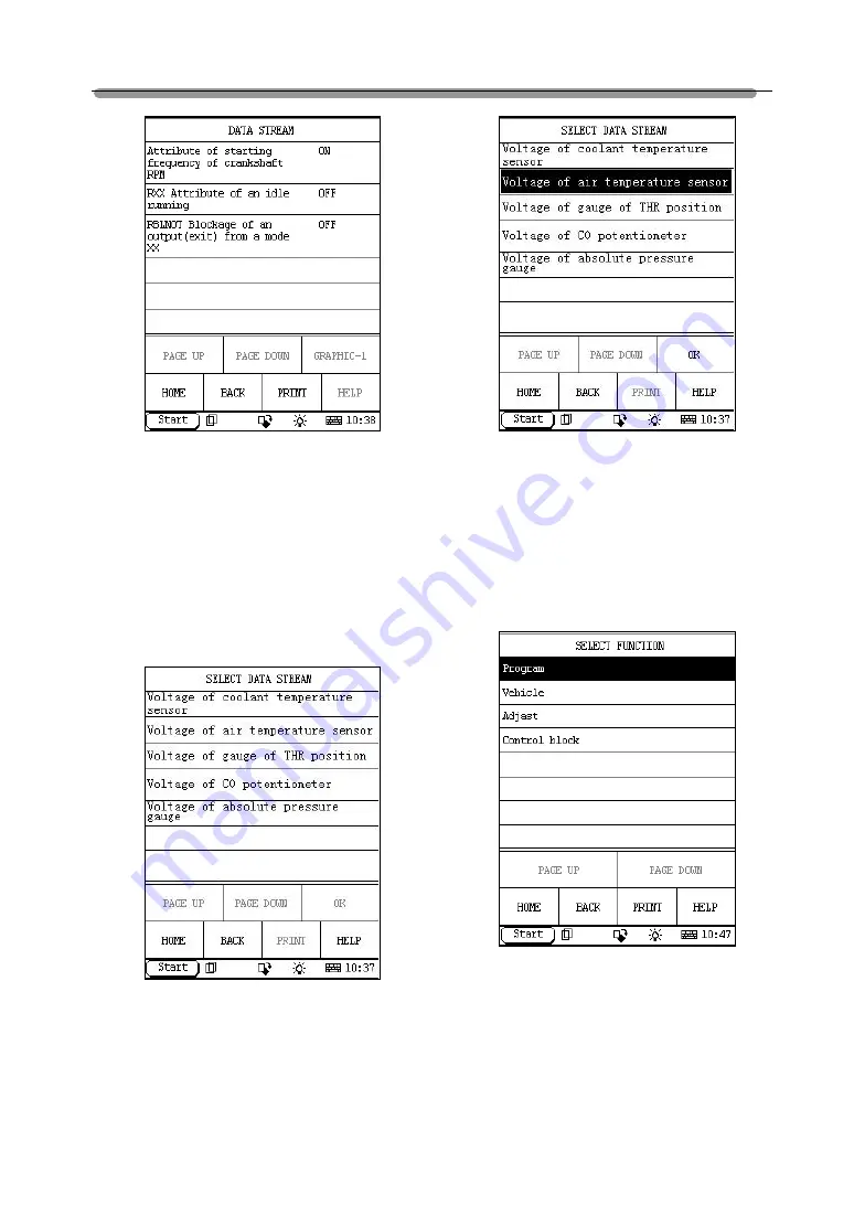
Figure 22
To view the live data stream, click the
corresponding items to select as shown in
Figure 23.
Figure 23
After selecting, click [OK] to display the live
data stream.
Passport
Click [PASSPORT] in the function menu. X-431
will display the sub-function menu as shown in
Figure 24.
Figure 24
Program
Click [Program] in the passport function menu.
The screen will display the data stream value
related to program as shown in Figure 25.


