background image


-      - 

9


Control Panel 


4 Control Panel  


4.1 Components of the Control Panel  


The control panel consists of the following elements:  
 

1.  Main power switch: 

connects and disconnects the ultracool unit 

from the power supply. 


2. On-Off switch: 

starts up the different elements that make up the 

ultracool unit.  


3. Water gauge: 

indicates the working pressure of the pump.  


4. Control thermostat: 

indicates the cold water temperature at the 

outlet of the ultracool unit and enables it to be regulated.  


5. Pump indicator: 

this remains lit when the pump is working.  


6. Compressor indicator: 

this remains lit when the compressor is 

working.  


7.  Water level alarm indicator: 

this is lit when the water level in the 

tank is too low. It causes the ultracool unit to stop. 


8.  Low flow/temperature control indicator:

 This flow control can stop 

the compressor when there is no water circulation through the 
external water circuit. In this case some flow still circulates inside the 
chiller. The temperature control can also stop the compressor when 
you try to reach water temperatures below 7ºC (45ºF). To be able to 
reach temperatures below that contact an authorised technical 
service. 


9.  Low refrigerant pressure alarm indicator: 

this is lit when the 

pressure of the refrigerating circuit is below the minimum allowed. It 
causes the refrigerant compressor to stop. 

UC-140 I

NDI

GO 

 50/

60Hz 29.

01.

03

 rev

. 0 

Summary of Contents for Ultracool Superplus series

Page 1: ...OPERATION MANUAL ultracool mini 0140 Indigo Ref MI 080 Rev 1 Date 30 04 03 50 60 Hz...

Page 2: ...The basic maintenance as indicated in point 5 1 should be carried out by properly trained personnel and if necessary under the supervision of a person qualified for this job ultrafilter personnel or p...

Page 3: ...t up of the ultracool unit 7 3 3 Chiller strat up 8 4 Control Panel 4 1 Components of the control panel 9 4 2 Control thermostat 10 4 2 1 Operation 10 5 Maintenance 5 1 Basic maintenance 11 6 Troubles...

Page 4: ...ded application in order to undertake additional safety measures if necessary 1 2 Safety regulations The operator has to observe the national working operating and safety regulations Also existing int...

Page 5: ...compressor The ultracool unit must be transported by palet jack or forklift truck 2 3 Site The ultracool unit must be installed in an atmosphere where the range of temperatures is within the indicated...

Page 6: ...nstallation the concentration of ethylene glycol should be checked Do not use automotive antifreeze Use lab grade ethylene glycol or refrifluid only Do not use an ethylene glycol concentration above t...

Page 7: ...r outlet of the ultracool unit and a solenoid valve in the water inlet The supply of this solenoid valve will be carried out by terminals designed for that purpose see electrical diagrams 2 7 Electric...

Page 8: ...of the ambient air Nominal 25 C 77 F Minimum 15 C 5 F 2 Maximum 50 C 122 F 1 For ambient temperatures below 5 C 40 F it is necessary to add ethylene glycol to the water of the circuit see point 2 4 3...

Page 9: ...ial start up To do so start and stop the ultracool unit using the On Off switch it is easier to see the turn direction when the pump is stopping In the case of the pump rotating in the opposite direct...

Page 10: ...when the compressor is working 7 Water level alarm indicator this is lit when the water level in the tank is too low It causes the ultracool unit to stop 8 Low flow temperature control indicator This...

Page 11: ...probe In the 50Hz version the display shows the temperature in C and in the 60Hz version it shows it in F as depicted above Setting the temperature Follow these steps to introduce the required workin...

Page 12: ...r filter if the pressure drop exceeds 0 5 bar 8 psi change the filter element Monthly With the Unit disconnected Main power switch Off clean the condenser with a blast of compressed air from the insid...

Page 13: ...ation stopped Check the motor fan fuses If the problem persists contact authorised technical service Disconnect the chiller On Off and Main power switch both Off see point 4 Open the front panel of th...

Page 14: ...following codes LO HI E0 Er2 EE The temperature has been below the setpoint for some minutes The temperature has been above the setpoint for some minutes Thermostat or temperature sensor is faulty If...

Page 15: ...5 kW 1 1 1 0 max flow 4000 17 6 4000 17 6 min flow l h US gal min 400 1 8 400 1 8 max pres 6 3 91 6 3 91 Water pump min pres bar psi 3 3 48 3 3 48 Water tank volume litre US gal 100 26 100 26 Water co...

Page 16: ...15 8 Log Book 8 Log Book 8 1 Log Book Date Remarks Signature UC 140 INDIGO 50 60Hz 29 01 03 rev 0...

Page 17: ...below 50 S cm The product refrifluid supplied by ultrafilter includes in its composition an anticorrosive bactericide and antifreeze until 7 C 19 4 F It has the following characteristics Parameter Lim...

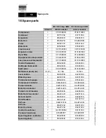
Page 18: ...6003 E5326003 Sight glass 1 0107397000 0107397000 Refrigerant gas kg lb 14 31 R 134a R 134a Level control 1 E4202004 E4202004 Water by pass 1 E2301002 E2301002 Pump pressure gauge 1 E5544014 E5544022...

Page 19: ......

Page 20: ......

Page 21: ......

Page 22: ......

Page 23: ......

Reviews: