background image


M

M

M

E

E

E

R

R

R

C

C

C

U

U

U

R

R

R

Y

Y

Y


U

U

U

S

S

S

E

E

E

R

R

R


M

M

M

A

A

A

N

N

N

U

U

U

A

A

A

L

L

L


43


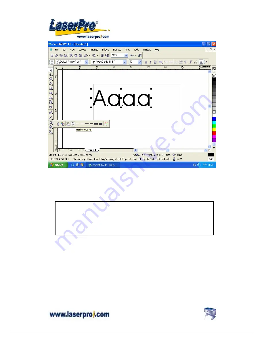
3. Change the text’s outline color by 

right clicking

 on the desired color on CorelDraw 

Color Palette. 

Notice 

If the width of the line to be cut is not set at minimum value, the laser is going to performing 
etching instead of vector cutting. The laser unit looks like engraving from left to right and right 
to left instead of cutting.     

Summary of Contents for Mercury

Page 1: ...USER MANUAL MERCURY ...

Page 2: ...COMMENDED CONFIGURATION 18 Computer 18 Scanner 18 Software 18 III HARDWARE INSTALLATION 19 Cabling Connection 19 Parallel Transmission 19 Serial Transmission 20 Interface for Macintosh 20 Exhaust Ventilation 20 IV SOFTWARE INSTALLATION 21 Install LaserPro Mercury driver to PC 21 V OPERATION 21 Environment 21 Flexible Utility of Your Memory Buffer 21 Am I in Multiple File mode or Single File mode n...

Page 3: ... NU U UA A AL L L 2 VII TROUBLE SHOOTING 64 Quality Problems 64 Non operational Problems 64 Appendix A 3D Function 65 Tip for 3D Application 65 APPENDIX B Application Parameters 67 Engraving Parameter 67 Cutting Parameters 68 APPENDIX C Specification 69 Optional Items 69 ...

Page 4: ...ondition but not recommended Press AUTO FOCUS the table will move upward and stop at the focal positionautomatically 8 The following is an example by using CorelDRAW V 11 Please ready the engraving graphic in CorelDraw and follow the instruction below to start work 1 Layout 2 Page Setup 3 Set from Printer choose Portrait 4 OK 5 Edit desired file picture etc 5 File 6 Print 7 Properties 8 Options ch...

Page 5: ...low the steps Tools Color Management Color Management Off OK 2 When operating with CorelDRAW V 11 or later version please choose Layout Page Setup Set From Printer 3 When using the available artworks from the Clipart of CorelDRAW to prevent the hidden vector lines shown on your engravings Please do as follows Choose a file from Clipart go to Bitmaps Convert to Bitmap after converting the file go t...

Page 6: ...s may cause sever eye damage if appropriate safety goggles are not worn NOTE Each LaserPro laser machine is equipped with a safety goggle if you need another one please contact LaserPro for it or try to get one that meets the following specification 190 398 nm OD5 10 600 nm OD5 Visible light transmission 92 9 3 Do not attempt to modify or disassemble the laser system at any time 4 Wear appropriate...

Page 7: ...ith a safety interlock system that automatically shuts off the power supply to the laser whenever the top or front door is opened There are magnets on the top and front door which activate this safety mechanism Do not attempt to remove or modify these magnets or any other component of the safety interlock system Warning Label On the surface of Carriage On the front cover of Laser Tube On the front...

Page 8: ...ife cycle of the laser source The life cycle of laser source is around 20 000 hours however it can be re filled and should be done by your dealer 3 What is the main purpose of air assist system The air assist system can provide a much better engraving cutting effect as it will blow away vaporized particles and prevent fire due to overheating 4 What does cutting table do The cutting table also know...

Page 9: ...his special design is to prevent the back door being opened without notice during operating However you have to use magnetic devices to short the connector of the magnetic switches on both side of the front door while opening for engraving extremely long work piece When doing so make sure that you wear safety goggles to operate the machine ...

Page 10: ... Air inlet connect to air compressor Air Flow Adjuster Press the ring to pull out the air tube Air Flow Fixer Control Panel Laser Source Front Door Top Door Air inlet connect to air compressor Valve Press the ring to pull out the air tube Air Flow Fixer Turn clockwise to decrease the air flow and counterclockwise to increase the air flow Please avoid turn off ...

Page 11: ...o the right layout Unscrew and remove the panel Unscrew and remove the dust prevention box Unscrew and pull out 1 mirror carefully without touching the surface of the mirror Step 1 Step 2 Step 3 Laser source inside Back Panel Back Door Top Door NOTE Please refer to Fig 25 and follow the instruction for the basic maintenance of mirror Motion System ...

Page 12: ...or Y axis Belt Focal Sharp Auto focus Gauge Manual Focus Gauge Holder Mirror 4 and Focus Lens inside Dust Prevention Box Mirror 2 inside Mirror 3 Holder X axis Bearing X axis Belt Bearing Track Y axis Belt Magnetic Sensor for Dual Head Port for Rotary Attachment Release the Screw to Pull Out the Mirror ...

Page 13: ...r LENS MANUAL FOCUS GAUGE 1 5 Option Purple Blue same as 2 0 2 0 Standard Blue Blue 2 5 Option Gold Gold 4 0 Option Red Red Manual Focus Gauge Holder Insert to the hole of the holder for manual focusing Mirror Lens 2 0 2 5 or 4 0 Slot position for Lens 1 5 only Auto Focus Gauge Focal Sharp Manual Focus Gauge Focus Carriage Assembly Focus Probe ...

Page 14: ...he engraving table Ensure the two screw holes should match the two corresponding holes on the table and the white mark of the left side align to the position of 24cm 9 45 inch on the ruler then tighten the screws 3 Plug the cable of the rotary attachment into the port in the middle front of the engraver 4 Turn on the power and the engraving table moves down to the lowest position automatically ...

Page 15: ...aximum diameter of the loaded object is 180mm and the limited loading weight is 7 Kg 15 4 Lb 1 Measure the diameter of the engraving area for setting up the software operation refer to Software Operation Fig 20 before engraving 2 Lift the lever loading the engraving object slide the adjustable end to the bottom of the object firmly then lower the lever of the fixture to secure it in place shown as...

Page 16: ...on you want Moving the red point from rotary home position at the base of the padded rubber wheel to the open end of the engraving object the Offset value refer to Fig II Software Operation Fig 20 will be displayed on LCD Base of the padded rubber wheel Open end of the engraving object lever O motor Adjustable end NOTICE When doing the Print Setup under print driver setting please always choose La...

Page 17: ...Connect the air assist tube of the dual head with that of original carriage by T connector Step5 Screw the metal frame which is attached to the right side of dual head to the original lens carriage Step6 Turn on the power to test whether the dual head is installed properly During initiation the system will detect the dual head carriage when it moves the lens carriage to front right side so it woul...

Page 18: ... 1 Keep the screws on the lens carriage after taking off the dual head 2 Put the black cap on the T connector after taking off the dual head to prevent air flowing leaking 3 Please choose dual head item from Paper option of printer properties before outputting a graph with dual head carriage ...

Page 19: ... following CPU Pentium at least DRAM 32 MB RAM or up FDD One 3 5 1 44 MB floppy HDD 1 2 GB Hard Drive or up SVGA 15 Super VGA Monitor On Board Parallel Mode Setup from PC BIOS SPP Preferred Mode ECP Cable length less than 1 8meters Scanner Flat Bed Minimum resolution 200 DPI Software GCC driver designed under Window 95 or higher level Windows Window 95 or higher CorelDRAW Version 7 0 or higher ver...

Page 20: ...has been design to switch from 100 240 VAC automatically 100W engraver has to use 220 240 VAC only 3 The engraver can communicate with a computer through either a serial RS 232C or a parallel port Centronics Parallel Transmission Connect a parallel cable to the engraver parallel port then to the parallel port of the host computer Caution Never use a mechanical switch box when a second printer port...

Page 21: ... to the engraver serial port then to the serial port of the host computer Interface for Macintosh To operate the engraver with a Macintosh computer e g Power Mac you need a MAC modem cable DIN8 to DB25 as an adaptor to connect to the RS 232C cable Exhaust Ventilation 4 inch diameter flexible hose Seal Clip Exhaust Blower Connect to an air filter or exhaust air outside of the building Air Outlet ...

Page 22: ... GCC driver disk from the floppy drive and store in a safe place V OPERATION Environment z A clean well ventilated room with a temperature of 15 25 60 78 Strongly suggested the temperature of 25 and a relative humidity between 30 and 40 as an office type environment z Avoid from unstable voltage supply z Short path for an effective air exhaust z Have a fire extinguisher available at any time Flexi...

Page 23: ...nction keys should be operated under STOP condition 3 NEXT FILE and DELETE keys are invalid under Single file mode Single 1 File Ok ENTER Change or LaserPro MERCURY Firmware V x xx Copyright 200x Initializing Please wait Set memory buffer Yes ENTER End operation ESC Z init AF position Table moves down about 50mm Press FUNCTION key Press ENTER key Multiple 100 Files Ok ENTER Change or Single No Rep...

Page 24: ...alizing Please wait Table moves down about 50mm automatically File Speed Power DPI Copies File Speed 00 00 Power STOP DPI Multiple file status Under STOP condition Press START STOP turn to STOP condition File x file name Speed xx x 00 00 Power xx PPI xxxx DPI xxx xxx K Send a new file from host computer then press NEXT FILE to show the file name on LCD Press NEXT FILE to get a desired file Press S...

Page 25: ...te and 10 seconds Press START STOP key turn the engraver to STOP condition LCD shows as follows Under STOP condition AUTO FOCUS and all other function keys can be operated while NEXT FILE and DELETE keys are invalid under Single file mode z Multiple File Mode Turn on power Mercury is under STOP condition and all function keys can be operated Laser engraver is ready to receive a file LCD shows as f...

Page 26: ...lens press AUTO FOCUS key to save the new focal length in memory LCD will show as follows NOTE 1 0 0 mm means the focus position is the Z axis home position of the Working table Above this position the value is negative while below this position the value is positive 2 Whenever the motion system or working table has ever been adjusted by a technical person please press AUTO FOCUS key to get an ini...

Page 27: ...r in the buffer PPI means pulse per inch File shows the current working file number Press NEXT FILE each time will increase 1 i e 1 2 3 100 and recycle the counting Once the buffer has received up to 100 files the LCD shows If a file received is out of memory the LCD shows RED BEAM On Off red beam SPEED Set up laser speed for desired effect When working without using MERCURY s driver lower case pr...

Page 28: ...inue the job POWER Set up laser power for desired depth and effect Other conditions are same as stated in SPEED PAUSE Temporarily stop the job during cutting or engraving RESUME Continue the temporarily stopped job DEL FILE This key delete file is valid under Multiple file mode only Press DEL FILE again to delete the file and LCD shows Delete current file Sure press again No ESC Now deleting curre...

Page 29: ...nsferred without saving in the buffer therefore once you want to repeat the job you have to re send the file from the host computer Under Multiple file mode you can engrave one job while transfer and design the next simultaneously until reaching 100 files limit or memory is used up Press FUNCTION key Single 1 File Ok ENTER Change or Set memory buffer Yes ENTER End operation ESC Z init AF position ...

Page 30: ... to the bottom of the engraver After initializing as long as you have not pressed AUTO FOCUS key you can go into this function and move the working table back to the power on position Once the AUTO FOCUS key has been used the last auto focus position has been saved in the memory Therefore the table will move to the last auto focus position by using this function Z init AF position Yes ENTER End op...

Page 31: ...y using this function when setting under Multiple file mode This function is invalid under Single file mode Once you stop or complete a job under Single File mode the file won t be saved in the buffer Delete all files Ok ENTER End operation ESC Select lens Are you sure Sure ENTER No ESC Select lens Yes ENTER End operation ESC Select unit ENTER ENTER ...

Page 32: ...ults in a straighter cut in thick materials The longer the focal length the bigger the beam spot size Although it is not ideal for high resolution image engraving The large spot size of low resolution lens can spreads the laser s heat over a larger area which helps minimizing melting thus can be applied to engrave certain kinds of plastics Select les Yes ENTER End operation ESC Select unit 2 0 inc...

Page 33: ...tion and cutting speed is 3 or above under vector mode the power control is enabled If set in Disable the power control is disabled Default Enable Select unit Yes ENTER End operation ESC Set EOF alarm Set power ramp Yes ENTER End operation ESC Select unit ENTER Enable Ok ENTER Change or Change or Disable Ok ENTER Change or ENTER ...

Page 34: ...A AL L L 33 Select unit Set unit in Metric or English NOTE means default or current setting Set EOF alarm Yes ENTER End operation ESC Tune Autofocusing Select unit Yes ENTER End operation ESC Set EOF alarm ENTER Metric mm Ok ENTER Change or or English inch Ok ENTER Change or ENTER ...

Page 35: ... L L 34 Set EOF alarm If set in Enable condition a beep tone sounds when End OF File Set EOF alarm Yes ENTER End operation ESC Tune Autofocusing ENTER Enable Ok ENTER Change or Disable Ok ENTER Change or Change or Tune Auto focusing Yes ENTER End operation ESC Select setup 1 16 ENTER ...

Page 36: ...sing position then press ENTER ENTER Tune Autofocusing Yes ENTER End operation ESC Select setup 1 16 Press AUTO FOCUS key then FUNCTION key select the function Tune Autofocusing If you have not pressed AUTO FOCUS after power ON If you have ever pressed AUTO FOCUS after power ON Attach manual focus gauge to the carriage and press arrow key up and down to position the working table in focus then pre...

Page 37: ...OWER key to change Press SPEED key to Power change speed Setup 1 Ok ENTER End operation ESC Select setup 1 16 Yes ENTER End operation ESC Select baud rate Change or ENTER Setup x Ok ENTER End operation ESC Select baud rate Yes ENTER End operation ESC Data bit parity ENTER POWER x x x End operation ESC SPEED x x x End operation ESC ENTER ENTER Save the desired cutting power for not using Mercury s ...

Page 38: ...e the speed of data transmission of serial port to communicate with the host computer Setting range 9600 19200 38400 57600 Defaults 57600 NOTE means default or current setting 57600 bps Ok ENTER Change or Select baud rate Yes ENTER End operation ESC Data bit parity ENTER xxxxxx bps Ok ENTER Change or Set data bit parity Yes ENTER End operation ESC Select language ENTER or ...

Page 39: ...d to check if data was received correctly or not The data parity feature is to adjust the byte format and parity type in order to communicate with the host computer through serial port 8 bits no parity Ok ENTER Change or 8 bits even parity Ok ENTER Change or Set data bit parity Yes ENTER End operation ESC Select language or ENTER Select language Yes ENTER End operation ESC ENTER ...

Page 40: ...t setting Select language Yes ENTER End operation ESC English Ok ENTER Change or ENTER or xxxxxx Ok ENTER Change or Do setup or send at least one file then NEXT FILE key select a file then START Do setup or press STAR key then send only one file Single file mode ENTER or ESC Multi file mode English Polish Italian Japanese Deutsch Turkish ...

Page 41: ...ge size to be the same as the printer s paper size Ensure the Normal Paper and Layout options are checked Step4 Click OK to complete the page size setting Notice Pre In some instances the LCD panel shows a message of Graph was clipped or the laser engraver is engraving at some strange location in some unpredictable way The result engraved artwork is scrapped Post This is caused by the mismatch of ...

Page 42: ...M M ME E ER R RC C CU U UR R RY Y Y U U US S SE E ER R R M M MA A AN N NU U UA A AL L L 41 Step5 Check the Page Size has changed ...

Page 43: ...es raster engraving or vector cutting based on the outline width of an object Therefore to achieve a vector cutting please set the text s filled with white color and the outline to its thinnest width in CorelDraw How to perform vector cutting 1 Select the text in which the change applies by clicking on the text 2 Change the text s fill color to white by left clicking on the white color of CorelDra...

Page 44: ...s outline color by right clicking on the desired color on CorelDraw Color Palette Notice If the width of the line to be cut is not set at minimum value the laser is going to performing etching instead of vector cutting The laser unit looks like engraving from left to right and right to left instead of cutting ...

Page 45: ... U US S SE E ER R R M M MA A AN N NU U UA A AL L L 44 4 Change the outline to its thinnest width by right clicking on the selected text 5 Go to the Properties option 6 Click on the Outline tab and change the Width to its thinnest dimension ...

Page 46: ...ill do the letter cutting C Raster Engraving Laser engraver prints raster as grids or dots of individually pixels any digital or scanned images can be processed by a laser engraver When doing raster engraving the laser would move from left to right or right to left After the image or graphics is ready please go further to the laser printing operation as next paragraph is shown ...

Page 47: ... CU U UR R RY Y Y U U US S SE E ER R R M M MA A AN N NU U UA A AL L L 46 Printing Mercury Driver Editing After completing the editing job choose File Print and click Properties to access Mercury driver parameter settings ...

Page 48: ...ng type The gray areas of image will be filled with different dot grid density from a 5 grade halftone with 2x2 dots to a 65 grade halftone with 8x8 dots 8x8 dithering type would presents the image into shading effect with more dots than the 2x2 dithering while the 2x2 dithering type would have smaller dots than 8x8 that produces higher resolution The dithering type choice would depend on the imag...

Page 49: ...r corner of the pattern result in a little triangle shape to imitate a shading effect c Bayer A random halftone pattern d 45 degree a halftone pattern consists of 45 degree matrix of dot arrangement 2 2 dithering 4 4 dithering 8 8 dithering Error Diffusion 2x2 Enhance Dithering 8x8 Enhance Dithering Dot Bayer Corner 45 degree 4 4 dithering 45 degree 6 6 dithering 45 degree 8 8 dithering ...

Page 50: ...ine will be invalid A 3 3D Mode With this function we can get the sculpture effect The engrave image must have gray levels The engrave image is effected by PPI DPI power and speed setting 3D Image File Sample Material Density Board A 4 Stamp Mode Mainly used in rubber stamp production Create a slope base of stamp characters by setting up the stamp parameter Normally the pitch number for engraving ...

Page 51: ... or be unstable Creating pitch is a way to add support to the thin lines and ridges The pitch value setting allows you to adjust the width of the ridges Broad pitch gives the maximum amount of support for each ridge Experiment with different pitch value settings in order to produce the stamp that is best suited for your application You can specify the size into the pitch box under stamp mode and a...

Page 52: ...lue bars are for the shoulders Adjust the value of power level by adjusting bar or the left click of mouse to edit the shape of the shoulders Add Border You may wish to include a thin or wide border around the outline of your stamp This can be done by creating outline greater than 001 thickness around the image When the Mirror setting is selected this outline will automatically be reserved as a ri...

Page 53: ...lor Fill mode Mirror When using a stamp the image needs to be reversed or mirrored in order to show up properly when the stamp is in use This setting will transfer right to left and vice versa Cutting out the Stamp After you have created a border around the stamp you may wish to have the Mercury s vector setting cut out the stamp from the rubber sheet To do this create a thin 0 001 red line around...

Page 54: ...tting and engraving These colors are referred to as PENS Try to think of each pen as a designated laser setting rather than as a color An image that is only black and white will use only one power and speed laser setting Black An image that includes black red and blue colors will use three different assigned power and speed settings In order to utilize up to 16 different pens make sure your graphi...

Page 55: ...he speed that the motion system travels when cutting or engraving straight lines The machine will automatically slow down when it is cutting or engraving curves B 3 Power Power setting here would decide the laser s power during operation The range is from 0 1 100 The percentage represents the power of each laser pulse fired Power and speed work together to determine the depth of a cutting and or e...

Page 56: ...t the image resolution of the engraving Higher DPI settings will have cleaner and deeper engravings but will take longer to complete Lower DPI settings will have coarser and shallower engraving but will take less time to complete Experiment with different settings to get your desired effect You can find the DPI function at Mercury driver Properties Option B 7 Save Parameters Setting Each job may r...

Page 57: ...s with printer driver parameters setting inside or can be saved a s the default settings in Mercury driver for future files 2 Please make sure your ID to log in the computer is set to Administrator level therefore OS of 2000 XP can allow you to save parameter settings File parameter setting save delete or load function Review and select the saved file parameter setting here ...

Page 58: ...For examples adjust the scale by 10 to enlarge the object s size by 10 1000 C 2 Position mode options Home Focus carriage goes back to the upper right position after finishing a job Without Home Focus carriage stops at the last position of a data file You can engrave inside a bowel or a concave object to prevent hitting the object Relative Move You can place the focus carriage at any place you wan...

Page 59: ...ng vector line and raster image the laser would take the vector line as raster data and print the whole graphics as raster engraving image Vector sorting When your image has one vector cut area enclosing another vector cut area this setting will automatically direct the laser to cut out the inside enclosure before moving to the outside image Optimization This is another setting that will automatic...

Page 60: ...add border at image edge for a better output of the stamp image You must select Image Invert under stamp mode when using border As for the figure below you can specify the border X and Y If you chose the Cluster and want to have border the border X and Y must be less than the Distance D you specified D Paper Settings These settings are included in Mercury driver Properties Paper They are used to a...

Page 61: ...r I INTRODUCTION Diameter Set up the diameter of the engraving area Circumference Diameter x 3 14159 Offset The distance from the open end of the engraving object to the base of the padded rubber disk The offset value will be displayed on the LCD screen D 4 Dual Head When working with Dual Head the function of Rotary Fixture is disabled and vice versa The working size for dual head is 305mm x 458m...

Page 62: ...et rid off any debris built up in the bearing tracks 4 Bearings Hold a dampened cotton swab against the bearing and moving the motion system by hand to clean each bearing 5 Mirrors and Lens The focus lens and the mirror located on the carriage are the two components most likely to require frequent cleaning Caution Don t scratch out the soft coating of the mirror s surface Excessive cleaning the mi...

Page 63: ... Y U U US S SE E ER R R M M MA A AN N NU U UA A AL L L 62 INCORRECT Do not use cotton swab to rub clean the mirror CORRECT Lens Tissue Pull the tissue one direction gently after the cleaner has been absorbed evenly Lens Cleaner CORRECT ...

Page 64: ...ge Pull out focus lens carefully 2 Flood the focus lens with lens cleanser on both sides then using a cotton swab or lens tissue to dry off the remaining solution gently 3 Do not touch the lens surface with your bare hands or press down hard with any cleaning material Remove Front Cover Mirror L Loading hole for manual focal tool Auto focus gauge Focal Sharp Top Screw ...

Page 65: ...amaged or need to be clean Non operational Problems z Laser beam does not generate 1 If the red alignment beam is not revealed the laser beam is misalignment Adjust reflection mirrors for exact focus 2 If the red alignment beam is revealed please check the driver power The laser power may be too low to be detected Please increase the percentage setting of the Laser Power from the software driver o...

Page 66: ...ose shown below When image is ready choose 3D Effect as the output mode in the driver Sometimes some material shows better effect if you run the job with 2nd pass with laser out of focus Especially with acrylic the 2nd pass will smooth out the surface For engraving wood as it burns easily and leaves blackened surface after the 1st pass it is necessary to run the 2nd pass to remove the burned surfa...

Page 67: ...ial 1cm Acrylic by Mercury 25W Lens 2 inch Step Speed Power DPI PPI Focus Remarks 1 25 100 600 auto Auto Focus 3D Mode Engraving 2 25 100 600 auto Lower down table 2 5mm 3D Mode Engraving 3 100 100 600 800 Lower table again 2 mm Black and White Mode Polishing 4 0 2 100 500 auto Move table up 1 3mm Cutting off ...

Page 68: ...0 100 L 50 25 100 Leather L 12 60 100 L 25 30 100 L 50 15 100 Mat Board L 12 100 50 L 25 100 100 L 50 50 100 Padauk L 12 100 30 L 25 100 60 L 50 85 100 Sign Vinyl L 12 50 100 L 25 25 100 L 50 12 100 Rubber L 12 100 8 L 25 100 15 L 50 100 30 Brass Coated L 12 100 100 L 25 50 100 L 50 25 100 Glass L 12 100 30 L 25 100 60 L 50 85 100 Crystal L 12 100 30 L 25 100 60 L 50 85 100 Poly buttons L 12 100 3...

Page 69: ...0 0 4 L 50 100 1 8mm L 25 100 0 2 L 50 100 0 4 12mm L 25 100 0 2 Acrylic L 50 100 0 4 Rubber 2 5mm L 12 100 0 4 L 25 100 1 L 50 100 2 Backlite 1mm L 12 100 0 2 L 25 100 0 4 L 50 100 1 3mm L 12 100 1 L 25 100 2 L 50 100 4 4mm L 12 100 0 4 L 25 100 0 8 L 50 100 2 5mm L 12 100 0 2 L 25 100 0 4 Plywood L 50 100 0 8 Be noticed that above parameters are for reference only Various kinds of elements struc...

Page 70: ...etting per job Power Control Adjustable from 0 1 100 and 16 colors linked power setting per job Z Axis Moving Automatic Resolution DPI 200 250 300 500 600 1000 Computer Interface Print port and serial port for PC Memory Buffer 16MB standard and upgrade to 64 MB with SIMM modules Multiple file mode saves up to 100 files Display Panel 4 line LCD display showing current file name total working time L...

Page 71: ...M M ME E ER R RC C CU U UR R RY Y Y U U US S SE E ER R R M M MA A AN N NU U UA A AL L L 70 ...

Reviews: