background image

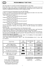
The function in the gr y boxes

e

are manufacturer programmed,

restored every time you enter

 programming function

the

Long acoustic tone

with optional buzzer

To skip to

the next function

Short acoustic tone

with optional buzzer

To confirm the

programming

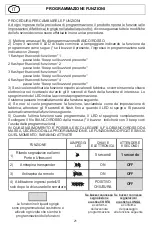
Alarm trigger delay

Doors and Ultrasounds

Transponder anti-car jacking

Remote anti-car jacking

Enable door / U.S. inputs

after closing the locks

FUNCTION

WAIT

8 SECONDS

ELETTRONIC

KEY

LED

FLASHES

OFF

5 second

1 second

OFF

OFF

ON

ON

POSITIVE

CDL CLOSE

PROGRAMMABLE FUNCTIONS

PROCEDURE TO CHANGE THE PROGRAMMABLE FUNCTIONS
Every time that a user enters in the programming procedure, the system resets all
functions to factory setting (grey in the table below); consequently, all the functions that

need to be modi ed must be carried out in a single procedure.

1) Connect to ground the programming wire WHITE/RED.
2) After 3 seconds the status LED starts to blink signalling the function to be set (*if the
buzzer is present, it will be indicated with 2 fast beeps):
1  ash for 8 seconds: function 1

led pause and 1 beep if the buzzer is present*

2  ashes for 8 second: function 2

led pause and 1 beep if the buzzer is present*

3  ashes for 8 second: function 3

led pause and 1 beep if the buzzer is present*

4  ashes for 8 second: function 4

led pause and 1 beep if the buzzer is present*

3) If it is necessary to modify the function, insert the electronic key to the receptacle
during 8 seconds of blinking. The turning OFF of the LED indicates the successful
programming.

Then the system automatically will skip to the following function
4)   it is NOT necessary to modify the function, leaving it in factory setup, wait 8 seconds

If

of blinking till the LED pause. It automatically will skip to the following function.
5)  hen the last fun tion is set (or con rmed as factory setting). the LED stop  ashing.

W

c

Disconnect the WHITE/RED wire from ground (*if is present the buzzer  the procedure

,

output is indicated with 3 fast beep).
TO EX  THE PROGRAMMING, AT ANY TIME IT IS POSSIBLE TO DISCONNECT

IT

THE WHITE / RED WIRE FROM GROUND.

THE FUNCTIONS MODIFIED UNTIL THE PROGRAMMING EXIT  WILL BE

,

ACTIVATED.

1)

2)

3)

4)

7

UK

Summary of Contents for 361

Page 1: ...ATIVE EARTH BATTERY 361 24V IMMOBILIZER FOR ALL VEHICLE WITH 24 VOLT AND NEGATIVE EARTH BATTERY IMMOBILIZZATORE con TRANSPONDER ATTIVO ATTIVATORE PER SATELLITARI E INGRESSO ALLARME PORTA IMMOBILIZATOR...

Page 2: ...ocket LED to the of dashboard drill aholewith diameter 10 mm IMMOBILIZER POSITIONING Remember the immobilizer installed in accordance with the manufacturer s instructions Place the immobilizer behind...

Page 3: ...orn negative intermittent signal NEGATIVE ALARM TRIGGER FOR PAGER SATELLITE ELECTRONIC SOCKET 10mm 361 100mA 100mA 1Amp 1Amp LIGHT BLUE Door contacts BUZZER optional ORANGE POSITIVE RED 12V 100mA BM1...

Page 4: ...J12 J10 OPTIONAL Identify the starting key wire Cut this wire Connect J11 to the starting key side ignition switch side and connect J12 to the starter motor side Weld and isolate the connections care...

Page 5: ...tment by the LIGHT BLUE wire doors contact and or the BLUE wire ultrasonic module These inputs are ready to receive an alarm signal when the transponder is not more present at least for 25 seconds The...

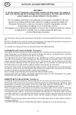
Page 6: ...are opened or when a hidden button is pressed the ignition is ON and and the transponder is not detected This function is excluded only by inserting the electronic key to thereceptacle LED 3 REMOTEANT...

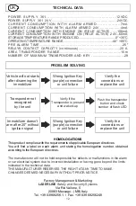
Page 7: ...is present itwill be indicated with 2 fastbeeps 1 ash for 8 seconds function 1 ledpause and1 beep if thebuzzer is present 2 ashes for 8 second function 2 ledpause and1 beep if thebuzzer is present 3...

Page 8: ...onder could be detected from the system It depends to the type of vehicle to the installation location of the into the unit vehicle to the presence or absence of obstacles between the vehicle and the...

Page 9: ...as soon as possible RESET PROCEDURE GARAGE EMERGENCY FUNCTION EXIT Switch on and keep the ignition ON Insert the ELECTRONIC KEY in the receptacle for 3 consecutive times The system will signal with TW...

Page 10: ...t devices to be learned to the unit when the memory is empty 1 transponder and 1 electronic key Refer to the paragraph SELF LEARNING PROCEDURE to learn additional devices DELETION OF ANY DEVICE PROCED...

Page 11: ...4 Battery Use a CR2032 battery This product contains a button coin battery do not swallow the battery Keep new and used batteries children If you far away from think the battery may have been swallow...

Page 12: ...VE 6 mA 24V 0 STORAGE TEMPERATURE RANGE PRODUCED 0 35 C OPERATING TEMPERATURE RANGE 40 85 C PRE ALARM TIME 25 RELAYS CONTACT CAPACITY continuous 20 A AREA TRANSPONDER RANGE 10m NUMBER OF MAXIMUM TRANS...

Page 13: ...zzer for 10 seconds then the sound becomes xed for 20 seconds by switching off the fuel pump relay BM1 for one second At the same time the intermittent clacson output and the negative Hazard command a...

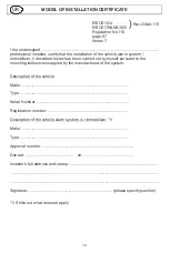
Page 14: ...mmobilizer described below has been carried out by myself pursuant to the 1 mounting instructions suppled by the manufactured of the system Description of the vehicle Make Type Serial Number Registrat...

Page 15: ...IZZATORE con TRANSPONDER ATTIVO ATTIVATORE PER SATELLITARI E INGRESSO ALLARME PORTA IMMOBILIZATORE 361 PER VEICOLI ALIMENTATI A 12 VOLT E NEGATIVO A BATTERIA IMMOBILIZATORE 361 24V PER VEICOLI ALIMENT...

Page 16: ...ietro il cruscotto o al cassetto portaoggetti o al sedile Al termine dell installazione deve essere saldamente ssato con i ssaggi forniti Il suo posizionamento dovrebbe offrire la massima protezione c...

Page 17: ...rme negativa intermittente clacson RICETTACOLO CON LED 10mm 361 100mA 100mA 1Amp 1Amp AZZURRO Pulsante Porta BUZZER opzionale ARANCIONE POSITIVO ROSSO 12V 100mA BM1 BM2 USCITA NEGATIVA PER COMBINATORE...

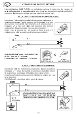
Page 18: ...il lo del motorino di avviamento Tagliare questo lo Collegare J11 al lato dove arriva il sottochiave lato interruttore di accensione e collegare J12 al lato dove viene fornito l impulso del motorino...

Page 19: ...de il veicolo segnale positivo e il transponder non viene rilevato per almeno 25 secondi l immobilizzatore attiva la protezione completa avviamento porte e ultrasuoni Quando l utente NON chiude la ser...

Page 20: ...essione di un pulsante nascosto se non viene rilevata la presenza del transponder 3 FUNZIONEANTI RAPINADAREMOTO vedere pag 27 Questa funzione permette di proteggere l autista daun tentativo di rapina...

Page 21: ...mmare come segue se il buzzer presente l ingresso in programmazione sar indicato con 2 beep 1 ash 8 1 per secondi funzione n pausa led e se il buzzer presente 1 beep 2 ash 8 second 2 per i funzione n...

Page 22: ...ponder etc L immobilizzatore viene disattivato automaticamente all avvicinarsi del TRANSPONDER al veicolo Il LED rosso in dotazione segnala l avvenuto riconoscimento del TRANSPONDER spegnendosi DESCRI...

Page 23: ...olo per emergenza ripristinare il funzionamento al pi presto RIPRISTINO FUNZIONAMENTO USCITAFUNZIONE GARAGE EMERGENZA Per ripristinare il normale funzionamento del sistema occorre Accendere e mantener...

Page 24: ...vuota Per procedere all apprendimento di ulteriori dispositivi occorre fare riferimento alla procedura AGGIUNTA DI NUOVI DISPOSITIVI PROCEDURA PER CANCELLARE TUTTI I DISPOSITIVI E APPRENDIMENTO DI DIS...

Page 25: ...siti contenitori In caso di eliminazione del transponder le batterie vanno scorporate e smaltite negli appositi contenitori NOTE PER LA MANUTENZIONE DEL PRODOTTO Pulsante g 1 g 2 g 3 ATTENZIONE 25 IT...

Page 26: ...Transponder sia presente acceso Premere il pulsante presente sul transponder e veri care i lampeggi del LED L immobilizzatorre non si inserisce dopo 25 anche con sottochiave in OFF Connessione del sot...

Page 27: ...a il buzzer interno intermittente per 10 secondi poi il suono diventa sso per 20 secondi spegnendo il solo rel pompa BM1 per un secondo In contemporanea si attivano anche l uscita intermittente Clacso...

Page 28: ...a di allarme immobilizzatore 1 descritta di seguito stata effettuata da me stesso in base alle istruzioni di montaggio fornite dal produttore del sistema Descrizione del veicolo M arca Modello Numero...

Reviews: