

This professional quality torque wrench comes with its
own certificate of test and calibration. The shaft of the
wrench is marked up in Newton metres (Nm), pound-foot
(lb.ft), kilogram metre (kg.m) and pound/inch (lb.in).
When selecting a torque wrench, determine what the
average or most common torque setting will be when you
use it. Then choose a torque wrench that will adequately
cover your anticipated torque specifications by selecting
one with an appropriate scale for your requirements.
This torque wrench is ideal for use in noisy environments
as the progressive torque build-up to the selected setting
is easily detected by three clear signals:
• Sight: the mechanism can be seen moving towards
the break point as the load is applied.
• Touch: the operator can feel the torque build-up and
then the very positive click at the break point.
• Sound: audible click at break point.
The handle is free to rotate on the wrench’s shaft so any
twisting of the handle when torqueing up a nut will not
affect the accuracy of the device. Changes to the torque
setting are carried out by pulling a lever-bar from the end
of the handle which is then rotated to obtain the correct
torque setting.
Unlike many other designs of torque wrench, the
mechanism pivots around the square drive and thus
the wrench is not length-dependant; there is no error or
variation to the application of the preset torque value, no
matter where the handle is held.
The drive shank can be pushed through the body of the
wrench which enables the wrench to torque up right-
hand or left-hand threads equally easily.
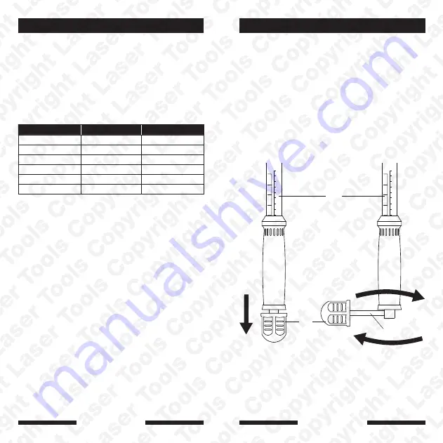
1. Refer to diagram. To adjust torque, first pull the end
cap (
A
) back to release the adjusting lever (
B
).
2. Rotate the adjusting lever clockwise to raise the
desired torque figure and anticlockwise to lower.
Refer to the dual scale (
C
) and adjust to the desired
torque.
3. Lock this figure by pushing the adjusting lever (
B
)
back into the body of the wrench and close the end
cap (
A
).
4. Commence tightening the fixing. You will feel and
hear the wrench mechanism give (or click) when the
set torque is reached. Immediately stop applying
tension to avoid over- tightening.
Instructions
Part Number
Drive
Range
7204
1/4"D
2.5 - 11Nm
7205
3/8"D
5 - 33Nm
7206
3/8"D
12 - 68Nm
7207
3/4"D
140 - 560Nm
7208
3/4"D
200 - 800Nm
7209
1"D
200 - 1000Nm
125
100
75
50
25
60
20
30
40
50
70
80
90
100
Nm lbf-ft
125
100
75
50
25
60
20
30
40
50
70
80
90
100
Nm lbf-ft
1
2
A
B
C
2
3
www.lasertools.co.uk
www.lasertools.co.uk
Our products are designed to be used correctly and with care for the purpose for which they
are intended. No liability is accepted by the Tool Connection for incorrect use of any of our
products, and the Tool Connection cannot be held responsible for any damage to personnel,
property or equipment when using the tools. Incorrect use will also invalidate the warranty.
It is our policy to continually improve our products and thus we reserve the right to alter
specifications and components without prior notice. It is the responsibility of the user to ensure
the suitability of the tools and information prior to their use.
Introduction