30
#109-S Motor removal and replacement - For Model
L1-S
Tools required:
7/64” ball driver
Time:
.050" hex driver
.75
Soldering iron
1/4" socket driver
Low profile 1/4" wrench
squaring check range
(s/t#50-1065 or equiv.)
A. Removal
1. Remove the top cover using a 7/64” ball driver.
2. Remove the wires from the motor terminals.
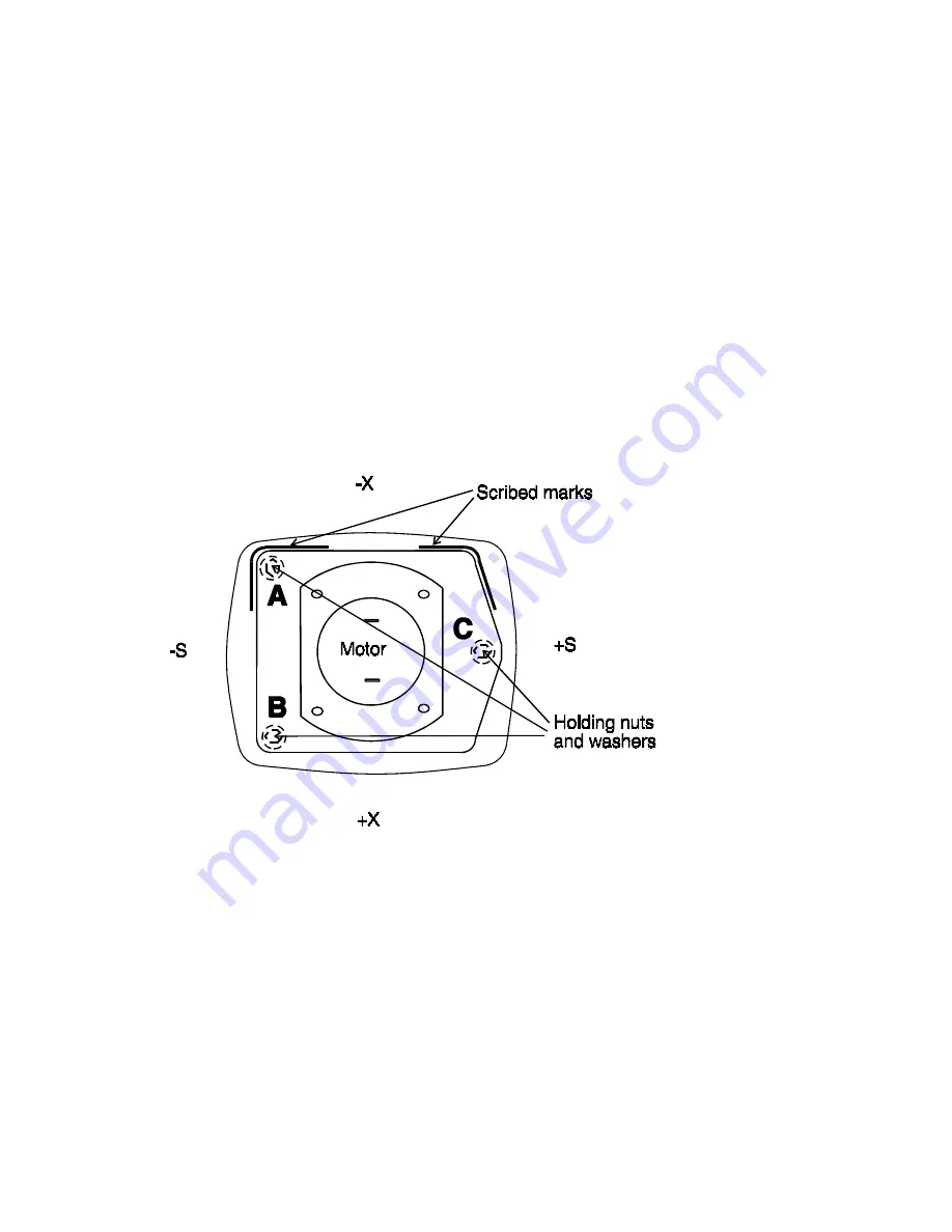
FIG. 5 Motor mounting and adjustment points
3. Scribe a mark around the motor mounting plate (this is to ensure proper
centering when installing the new motor assembly).
4. Remove the three holding nuts and washers.
5. Remove the motor assembly.
6. Using a .050” hex driver, loosen the set screw in the penta mirror base
and remove the mirror assembly.
B. Replacement
1. Install the penta mirror assembly onto the motor shaft, leaving
approximately 1/64” between the penta mirror base and the motor holding
screws.
Summary of Contents for pro shot L1-M
Page 1: ......
Page 3: ......
Page 6: ...3 External Parts Detail Model L1 M Fig 1 ...
Page 7: ...4 External Parts Detail Model L1 S Fig 1A ...
Page 8: ...5 Internal Parts Detail Model L1 M Fig 2 10 0495 LCD assembly ...
Page 9: ...6 Internal Parts Detail Model L1 S Fig 2a ...
Page 10: ...7 Housing Lighthouse Model L1 S ...
Page 11: ...8 Motor Problems Model L1 M Only ...
Page 12: ...9 Motor Problems Model L1 S Only ...
Page 13: ...10 Power Problems ...
Page 15: ...12 Calibration Problems ...
Page 16: ...13 Calibration Problems 2 ...
Page 17: ...14 Calibration Problems 3 ...
Page 18: ...15 Low Battery Indication Not cured with new Batteries ...
Page 38: ...35 PCB Layout ...
Page 39: ...36 Schematic for L1 M S ...
Page 41: ...38 ...


