background image

Issue 1

Page 15 of 24

EL-SMS-2G-TP / TP+ / PROBE-G USER MANUAL

Hardware Operation

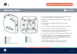
Power up LED sequence

When the unit is powered on, the following LED flash sequence is displayed:

Red LED, Green LED, No LED’s

LED Flash Sequences

Start up flash sequence

Red LED, Green LED  0.5s each

Status display
(standby mode)
Short push of status button.

4 green flashes = Setup not yet attempted.
5 red flashes = Setup attempted but failed.

1.5s red LED = Low battery

Setup mode sequence
5 second push of status
button

1 red flash every 5 seconds = Not ready to receive

SMS.

2 green flashes every 5 seconds = Ready to

receive SMS.

Status display (Run mode)
Push of status button

2 red flashes = In alarm condition (Highest priority)
3 red flashes = Low battery (Medium priority)
1 green flash = Running, no alarm conditions (Low

priority)

Stop monitoring

Green LED on for 3s then off for 3s followed by

reset.

Unit “Configured” status is cleared.

SIM Card Error

4 red flashes every second for approximately

10 minutes.

User Guide

Netlight LED Operation

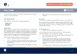
The orange Netlight status LED will show you the status of the internal 2G GSM

module when it is in use. The flash sequences displayed by the Netlight are as

follows:

Off

GSM module is powered off.

1 second flash

GSM module is not registered on a mobile network.

2 second flash

GSM module is registered on a mobile network.

Sounder

The unit is fitted with a sounder which is used to indicate various operating

conditions as follows:

Ready for configuration message

Triple beep

Configuration message received

Double beep

No configuration message received

OR message was not compatible
with the unit

Five short beeps

Summary of Contents for EL-SMS-2G-TP

Page 1: ...EL SMS 2G TP TP PROBE G USER MANUAL Temperature Monitor with SMS Alerts...

Page 2: ...your smartphone or tablet and and add a new device Use the mobile number that was supplied with your SIM card 7 If using Android select the device just added and press the Setup button 8 Con gure the...

Page 3: ...11 Setup Mode 11 Con guring the Unit 11 Run Mode 13 Stop Monitoring 13 SMS Retry Process 13 Security 14 Table of Contents Hardware Operation 15 Power Up LED Sequence 15 LED Flash Sequences 15 Netlight...

Page 4: ...3 Add the EL SMS device to your list by clicking the Add logger button at the lower right of the screen 4 Input the ELSMS device mobile number Optionally add a device name and notes regarding the devi...

Page 5: ...the icon for the device to a photo or reset it back to the default d DELETE DEVICE Removes the device from the App 6 Full Setup Tap the setting you wish to change See Fig 5 a Probe selection Allows y...

Page 6: ...bers that this ELSMS device should notify and select which messages they will receive See Fig 10 g Press the start button to send the con guration message to the EL SMS device 7 Viewing noti cations F...

Page 7: ...t to change 1 Download and install the App from the App Store iTunes 2 Open the App see Fig 1 Full Setup Con gure the device by tapping the options in the list 3 Select and enter the EL SMS device mob...

Page 8: ...fore a new alarm condition will be sent to you See Fig 5 8 Summary Interval The interval at which the ELSMS device will send you information regarding its status See Fig 6 9 Contact Information Input...

Page 9: ...Global System for Mobile Communications network to deliver the SMS noti cation messages and must be tted with a micro SIM card to allow them to connect to a GSM network and register These units use a...

Page 10: ...ever that actual delivery of the message is reliant on the mobile network and mobile operator s services operating normally User Guide Alarm Delay Operation These units allow a separate pre and post a...

Page 11: ...s ran at during operation When an attempt to setup the unit has been made and does not complete successfully User Guide When the unit is in run mode and the stop monitoring button sequence is pressed...

Page 12: ...to delays inherent in the GSM network such as network outages over subscription routine maintenance work message centre technical issues etc If a setup attempt does fail you can simply repeat the set...

Page 13: ...ondition is detected a battery low noti cation message will be sent The buttons are disabled whenever the unit is actively sending an SMS Stop Monitoring When the unit is in Run mode it can be put bac...

Page 14: ...n the summary message will be cancelled Regardless of the outcome the minimum maximum and average temperature data for the period will be reset 1EasyLog O ce 6 5 55 50 00000000000000000 00000000000000...

Page 15: ...es Low battery Medium priority 1 green ash Running no alarm conditions Low priority Stop monitoring Green LED on for 3s then o for 3s followed by reset Unit Con gured status is cleared SIM Card Error...

Page 16: ...mber has been con gured Using additional destination numbers will reduce the expected battery life User Guide Aerial and Signal Strength The unit uses a built in aerial to connect to the mobile networ...

Page 17: ...l time of the device used to send the con guration message by the amount that the con guration message was delayed Also note that the real time clock will be reset if the batteries are removed The clo...

Page 18: ...mation Date Time eld for con rmation that the real time clock has been set Current temperature Signal strength in bars where one is poor signal and ve is excellent signal Programmed rmware version Uni...

Page 19: ...h the message PrbErr followed by O or C for missing or broken probes Summary Message The summary message is sent at the interval speci ed when the unit was con gured The following information is shown...

Page 20: ...for a short circuit probe error probably caused by a faulty probe Setup Complete No SMS Rxd message report the probe errors as follows PrbErr Open is displayed for a disconnected probe error open circ...

Page 21: ...oduct may lead to excessive operating costs SMS Delivery SMS text messaging is a store and forward messaging system which uses message service centres to temporarily store messages until they can be d...

Page 22: ...signal strength shown in the last summary message was su cient for reliable operation SMS message centre issues Normal operation will resume when the network service disruption has ended Incorrect de...

Page 23: ...G Module Class 4 2W 850 900MHz Class 1 1W 1800 1900MHz Internal Antenna Penta band Embedded Antenna 50 Ohm Impedance Linear Polarisation 3dBi Gain VSWR 3 1 Battery Life 1 Year at 25 C daily summary me...

Page 24: ...major network operators infrastructure and generally o er their own customer service billing support systems marketing and sales personnel Short Message Service SMS Text messaging service allowing sho...

Page 25: ...EL SMS 2G TP TP PROBE G USER MANUAL Temperature Monitor with SMS Alerts...

Reviews: