4
Instructions and Maintenance Sheets
Electric Test Pump “HEP0180”
ASSEMBLY AND OPERATING INSTRUCTIONS
The components are shipped unassembled to prevent breakage or unnecessary bulk during transport or the stockage
in warehouse. Before starting operations, check if the pump has been labelled with serial number and technical data.
Keep package for further transports or stockage.
Assemble the device in accordance with the next procedure, first checking that you have all the necessary material.
Use PTFE tape on all threads to prevent any leakage.
Before starting any operation, clean the tank to eliminate any residue or waste.
To avoid pressure oscillation due to air in the system, it is necessary to purge the air circuit to fill the system
completely.
1.
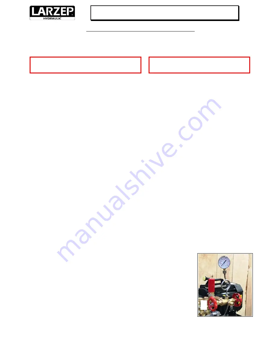
Assembly all components. The pump is provided with glycerin pressure gauge ø60, coil and double control valve.
2.
Place the pump body over the tank and fix it with the supplied screws.
3.
Screw suction pipe into the base of the pump.
4.
Screw the double control valve unit into the pump block. Screw the gauge tube vertically and mount the gauge. In
order to favour the immediate reading during the test, point the pressure gauge in the direction of the operator.
Remember to apply necessary seals to all components.
5.
Place the equipment on a flat and solid area.
6.
Fill up the tank and ensure the suction tube is completely submerged. Use anticorrosive, antioxidant fluid or a
mixture of water and emulsifiable oil in order to prevent oxide formation inside the machine.
Check the suction
filter before any testing.
7.
Connect one end of the hose to the pump and the other end to the system or equipment to test (pipe, tank,
valve, etc.).
8.
Before operating the pump always make sure pipe connections are clean and fully tightened up; all accessories
must be fitted correctly: suction tube with nut and filter, pressure gauge and hose for high pressure.
Always use
protective goggles, shoes and gloves.
9.
Verify that electrical requirements of the motor are according to the electric power supply in the plant. Then,
connect the motor to the power line. Check that the motor runs correctly.
Ensure good motor ventilation. Check
that motor can have enough fresh air flow from the chassis.
10.
Pre‐fill the system or equipment before starting the test with the same liquid that will be used for testing.
11.
To start the test, close the discharge valve B (right) and open the flow‐valve A (left) manually. There are two
handwheels on the control valve block for these two valves
.
12.
Switch on the pump and regulate the outlet value of the pressure using the red knob C,
this operates on a by‐pass designed to deliver the necessary pressure step by step.
13.
Check the pressure shown in the gauge and do not exceed the max. pressure.
14.
Once reached the required pressure, close the flow‐valve A, to maintain the same
pressure value in the element under pressure. Make sure there are no leaks.
15.
To finish the operation, open the discharge valve B and surplus liquid will run back into
the tank through a discharge pipe.
16.
To perform another test, follow the instructions from the beginning.
Replace the seals at least every two years.
No preventive maintenance is required.
If the pump is not used for a long time,
preserve package from humidity or
rain. The pump should be kept away from extreme temperature.
Ensure that all the equipment and accessories
are suitable for the maximum working pressure.
A
B
C
The pump must always be handled
and repaired by qualified personnel.


