background image

SoundAdvisor Model 831C

Setting Up the Event History Measurement

126

Module  17   

Using Event History Firmware

T

his module  shows  how  to  perform  a  measurement  using  Event  History,  a  feature  of

option 831C-ELA. This firmware upgrade provides event-based logging analysis and event

history data with manual or timed storage of statistical data and measurement history.

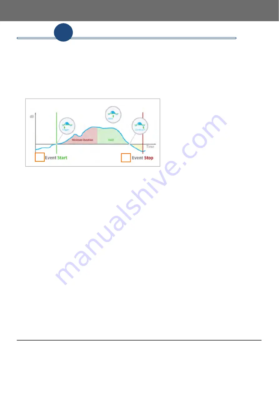
FIGURE 17-1  

Sound Event

1.

An event starts when the measured sound 

pressure level exceeds at least one 

Trigger 

Level

 and persists longer than the 

Minimum 

Duration

 you define. 

2.

An event stops when the sound level drops 

2 dB below the trigger level. This 2 dB 

hysteresis is to avoid the creation of multiple 

exceedances when the sound level is 

fluctuating at or near the trigger level.

In this module:

17.1 Setting Up the Event History Measurement ...................................................................... 126

17.2 Storing Event Data  ............................................................................................................. 129

17.2.1 Using (Continuous) Daily Auto-Store With Event History

17.3 Viewing Event History Data on the Events Tab ................................................................. 130

17.3.1 Viewing Octave Band and Spectral Events

17.4 Setting Advanced Event Triggers ....................................................................................... 132

17.4.1 Using Running Leq as an Event Trigger

17.4.2 Using 1/1 Octave and 1/3 Octave Event Triggers

17.5 Understanding Level and Dynamic Triggering  ................................................................. 134

17.5.1 Understanding Level Triggering

17.5.2 Understanding Dynamic Triggering

17.1  Setting Up the Event History Measurement

This section shows how to add some or all of the following capabilities to a measurement

setup file: Trigger Levels, Event History, Event Time History, and Alert Notifications.

2.

1.

17

Summary of Contents for 831C-FFT

Page 1: ...Larson Davis SoundAdvisor Model 831C Sound Level Meter Reference Manual...

Page 2: ...pographical errors PCB Piezotronics Inc will periodically update the material for inclusion in new editions Changes and improvements to the information described in this manual may be made at any time...

Page 3: ...1C 48 5 1 Understanding Calibration Values 5 2 Choosing a Calibrator 5 3 Reviewing the Calibration Settings 5 4 Calibrating Your SoundAdvisor 831C Module 6 Creating a Measurement Setup 54 6 1 831C Set...

Page 4: ...rmware Module 15 Using Measurement History 113 15 1 Setting Up a Measurement With Measurement History 15 2 Viewing Measurement History Data Files Module 16 Using Time History 120 16 1 Setting Up a Mea...

Page 5: ...sis Software Option 831C OB3 A 5 Event Logging Software Option 831C ELA A 6 Time History Software Option 831C LOG A 7 FFT Analysis Software Specifications Option 831C FFT A 8 PTB Approved Firmware A 9...

Page 6: ...31C refers to the full color screen G4 LD Utility software G4 connects your meter to your PC via USB WiFi or TCP IP With G4 you can calibrate the meter create setup files download measurements and ana...

Page 7: ...ing a Precision Acoustic Calibrator and store calibration history Time stamping for Lmax Lmin Lpeak max single event metrics Sync clock with PC attached GPS or Network Time Protocol NTP Create multipl...

Page 8: ...unications 1 3 Performance Features Large dynamic range 120 dBA RMS Detectors Slow Fast Impulse RMS Frequency Weighting A C Z Peak Frequency Weighting A C Z Any LevelTM Simultaneous measurement and di...

Page 9: ...ailable Items SoundAdvisor 831C Microphones 377B02 inch free field prepolarized microphone 50 mV Pa providing performance conforming to Class 1 sound level meter standards 377C20 inch random incidence...

Page 10: ...purchase date model and serial numbers for your instrument preamplifier and microphone 1 5 Available Options and Accessories In this section 1 5 1 Firmware Options 1 5 2 Hardware Options Accessory Kit...

Page 11: ...nt data 831C MSR Measurement History for the manual or timed storage of statistical data with all sound recording capabilities 831C SW Make direct USB communication with Sierra Wireless RV50X cellular...

Page 12: ...Pa providing performance conforming to Class 1 sound level meter standards Microphone Preamplifier Options 426E01 inch ICP Low Noise microphone preamplifier requires adapter ADP074 PRM2103 Outdoor mic...

Page 13: ...quare wave pulse measurement include a 100 kHz low pass T filter with the adapter ADP002 6 8pF BNC Input Adapter for inch 7 pF microphone equivalent ADP090 12 pF BNC Input Adapter for inch 12 pF micro...

Page 14: ...On or Off 2 2 5 Using the Power Control Page 2 3 Instrument Hardware Overview 16 2 3 1 Using 831C Buttons 2 4 Display Elements Overview 19 2 4 1 Changing Display Color Themes 2 4 2 Using Tabs and Pag...

Page 15: ...amplifier body To disconnect the microphone Lightly grip the 2 engraved lines on the microphone body and gently turn 2 1 2 Connecting the Preamplifier to Meter CAUTION Do not attempt to screw the prea...

Page 16: ...er Events and Indications 2 2 1 Using Battery Power Current Battery Voltage is displayed on the Power Control page To access the Power Control page press the Power button 0 In the Status Bar section o...

Page 17: ...the end of expected life the empty battery symbol begins to flash When the battery is no longer functioning the 831C stops running saves all data and instrument status then turns off When you power th...

Page 18: ...other external power source TAKE NOTE If you re using a power cable other than the one supplied with the meter use a 28 AWG or larger wire for proper charging Understanding Charging Status LED Indicat...

Page 19: ...h the same gauge wire to prevent excessive power loss 2 2 3 Understanding 831C Power Events and Indications Understanding a Low Voltage Shutdown Event The 831C preserves the service life of an externa...

Page 20: ...a power check If the supplied power is too low the low power icon displays over top of the first display For more information see Table A 5 Low Power At Boot Up Understanding Low Input Power Indicato...

Page 21: ...ware Overview FIGURE 2 5 831C Instrument Overview front 1 Standard 1 2 free field or random incidence microphone 2 PRM831 Preamplifier 3 Release button to disconnect the preamp from the meter 4 240 x...

Page 22: ...m storage 1 to 2 weeks See 2 1 4 Prepar ing the 831C for Long Term Storage on page 11 CAUTION DO NOT use the AC DC port as 1 AUX connector intended for use with USB mass storage cellular modem GPS hea...

Page 23: ...7 When running press Stop Store to stop press when the meter is stopped to store the measurement 3 9 Press Run Pause once to Run press while running to Pause press while Paused to resume the measureme...

Page 24: ...2 4 1 Changing Display Color Themes The 831C has a full color back lit LCD touchscreen and allows you to select your preferred color theme The Dark theme is featured in this manual For more informati...

Page 25: ...ys the meter measurement connection alert status and battery status as shown in Figure 2 8 FIGURE 2 8 Status Bar 1 Power Indicator 2 WiFi Status 3 SLM Indicator 4 Run Status 5 File Name 6 Measurement...

Page 26: ...e on the meter When the USB drive is reinserted the USB caution icon appears The meter notifies you that there is unsaved data and prompts you to Save or Delete the measurement data You cannot continu...

Page 27: ...the OBA Under Range Icon flashes Measurement Status Icons FIGURE 2 10 Measurement Status Icons If the touchscreen is enabled or if you re operating the meter remotely tapping the icon produces the fo...

Page 28: ...an also create a setup file using G4 LD Utility then transfer the file to the meter For more information see the G4 LD Utility Manual Mark Sound Type When you ve purchased and installed firmware optio...

Page 29: ...alibrate Calibrate the microphone for accurate measurement See Module 5 Calibrating Your SoundAdvisor 831C Setup Manager Setup measurement parameters and metrics See Module 6 Creating a Measurement Se...

Page 30: ...or Model 831C Display Elements Overview 25 2 4 6 Power Control Menu Overview To access the following actions on the Power Control menu press power 0 once Battery Information Display Brightness Power O...

Page 31: ...Measurement Setup LEARN MORE Depending on your measurement type and installed firmware options Modules 15 18 may be helpful while creating the measurement setup file Step 3 Calibrate your 831C as sho...

Page 32: ...e on an automated weekly schedule when using G4 and the 831C Scheduling firmware option 831C SCH which is available from Larson Davis LEARN MORE For more information on this feature see the G4 LD Util...

Page 33: ...h a network connection from the 831C to the Internet For more information see Module 13 831C Network and Connections Step 2 You may want to consider activating the 831C network and meter security feat...

Page 34: ...0 kB press Stop Store 7 to save it Before you begin another measurement download all internal data to an external drive or PC by using the Data File Manager or G4 LD Utility TAKE NOTE This option is n...

Page 35: ...d storage account see 9 11 Enabling or Disabling Cloud Storage on page 92 3 3 2 Using the 831C File Storage Calculator The Memory page on the Live view provides a helpful file storage calculator that...

Page 36: ...y in FFT Mode 47 4 1 SoundAdvisor 831C Display In SLM Mode In this section 4 1 1 Understanding the Live Tab 4 1 2 Understanding the Overall Tab 4 1 3 Viewing Weather Related Data 4 1 4 Understanding t...

Page 37: ...ighlight this metric press Enter 5 and select a metric to display 2 This is the metric you choose in the Any Level menu on this tab The default value is LAS To open the Any Level menu highlight this m...

Page 38: ...is is the Exceedance Trigger level you selected in the measurement setup About the Octave Band Analyzer Page TAKE NOTE This feature requires the 831C OB3 firmware option Four pages on the Live tab rel...

Page 39: ...elector between the following options Ref Set Reference and back to the Octave 3 View References 1 2 3 4 A A C and C 4 Save the current selected values to use as a reference by selecting Set Reference...

Page 40: ...er is installed this page provides information like temperature and humidity as well as desiccant maintenance information About the Power Page The Power page shows the meter status items as shown in F...

Page 41: ...re failing About the Memory Page The Memory page displays a helpful data storage calculator that can help you estimate the amount of storage a measurement might require as shown in Figure 4 8 FIGURE 4...

Page 42: ...ghting and detector from the measurement setup file It is the equivalent sound based on the run time of the measurement 3 The data graph presents info from beginning left to end right 4 This SLM metri...

Page 43: ...during the run time of the measurement A date and time of occurrence is recorded with this event About the Octave Band Analyzer Page Overall Page TAKE NOTE This feature requires the 831C OB3 firmware...

Page 44: ...the highlighted frequency band for the duration of the measurement Lmax Lmax is the maximum sound level of the highlighted frequency band The maximum spectrum is determined by the Max Spec setting Bin...

Page 45: ...at highlighted band About the Ln Percentiles Page Overall Page FIGURE 4 15 An Ln percentile is a statistical measurement of the level that exceeds the selected value n percent of the time The statisti...

Page 46: ...ach time a trigger level is exceeded during a run the counter for that level advances from 14 to 15 and the value displays in orange or red 1 of exceedances 2 Time of last exceedance About the Overloa...

Page 47: ...by Directive 2002 49 EC of the European Parliament and of the Council of 25 June 2002 relating to the assessment and management of environmental noise It is important to verify prior to the measureme...

Page 48: ...GURE 4 20 Sound Exposure Level Page About the Metrics Matrix Page Overall Page FIGURE 4 21 The metrics matrix page shows all the data the meter is always measuring in one page You can use the ENTER 5...

Page 49: ...ather readings in the following locations The Live Tab Weather page as shown in Figure 4 23 Live Tab Weather Pages The Overall Tab Weather Page as shown in Figure 4 24 In the resulting data for Event...

Page 50: ...Hail Max Rate in2 h Hail Accumulation in s In G4 weather related events and their triggers display in the following columns in the Event Time History data Gust Speed mi h Gust Dir Compass Direction 4...

Page 51: ...equency spectra for this meter are shown in Table 4 5 To adjust the graph scale do the following a Select the Menu softkey This opens the Live Menu Resume from pause Measurement reset Calibration reco...

Page 52: ...Tools 3 System Properties Step 2 Use the top right softkey to navigate to Displays Step 3 From the Start drop down menu choose the first page you want the meter data to display on Step 4 From the Tabs...

Page 53: ...ing a Calibrator 50 5 3 Reviewing the Calibration Settings 50 5 4 Calibrating Your SoundAdvisor 831C 53 5 4 1 Calibrating While Using Meter Security Lock Mode 5 4 2 Performing an E A Check 5 1 Underst...

Page 54: ...determined by the noise floor 9 14 dB LEARN MORE For more information about measurement range noise floor linearity range and max peak levels as they relate to different microphones and gain settings...

Page 55: ...ion e g meter moved to or from 85 kPa static pressure elevation Recalibrate first then enter values if needed Outdoor Measurement When using the 426A12 Outdoor microphone and power supply or the Model...

Page 56: ...selection from the Microphone drop down menu The actual value is calculated during calibration 2 If your calibrator has unique values use these fields to manually enter and save them 3 This preamp mic...

Page 57: ...ion Histories Tab in the G4 LD Utility Reference Manual Step 7 Navigate to the Calibration Certification tab which shows when the meter was last certified by the factory and when it is due for recerti...

Page 58: ...ge such as Calibration Out of Range verify that the dB level for your calibrator and your meter are the same then perform the calibration again Be sure to power the calibrator on each time 5 4 1 Calib...

Page 59: ...File List is the first page of the Setup Manager To edit a Setup highlight it then press Enter 5 The Settings line displays the name of the Setup you are currently editing 2 To navigate to other page...

Page 60: ...Meter Step 1 On the 831C go to Tools 3 Setup Manager Step 2 In the Setup Manager File list highlight the Default setup in the list and press Enter 5 This opens the Setup Manager pop up menu Step 3 Se...

Page 61: ...se the right softkey to navigate to the General tab as shown in Figure 6 3 These fields are optional FIGURE 6 3 Setup Manager General Tab 1 When set this value appears as a filename prefix for all mea...

Page 62: ...er In this example the period is the Leq of the last 1200 seconds of the measurement run time For more information see Module 17 Using Event History Firmware About Using the Gain Feature When using a...

Page 63: ...n Max and At Lmax in the Appendix C Glossary on page C 1 5 Spectral Ln values can be measured using 1 1 or 1 3 octave bandwidths If both 1 1 and 1 3 are selected in the Bandwidth setting Spectral Ln o...

Page 64: ...le 16 Using Time History Step 9 Use the right softkey to navigate to the Exceedance Triggers tab as shown in Figure 6 8 FIGURE 6 8 Setup Manager Exceedance Triggers Tab 1 SPL Trigger Levels When the m...

Page 65: ...l of 25 June 2002 relating to the assessment and management of environmental noise Because of these recommendations and the versatility of the standard on this point it s important to verify these val...

Page 66: ...exceedance with sound exceedance paused the wind speed must drop below the Hysteresis before the sound exceedance pause turns off TAKE NOTE The Larson Davis weather sensor SEN03x takes a running avera...

Page 67: ...s Step 1 To save your Setup and exit the Setup Manager select Close Step 2 In the Save dialog choose Yes to save your settings Step 3 Highlight and press Enter 5 on the name of the Setup you created S...

Page 68: ...59 Using Timed Stop Mode The measurement is initiated manually and stops automatically after the period you indicate Step 1 Select Timed Stop from the Run Mode drop down menu a Enter the measurement...

Page 69: ...stored in the Time hh mm ss field TAKE NOTE At the end of the Auto Store period the 831C saves measurement record to a new incrementally named data file throughout the day based on the Time hh mm ss T...

Page 70: ...nter a Start y m d date and Time and an End y m d date and Time where Time is the time of day b If desired select the checkbox in line with 2 and 3 to enter additional measurement periods Step 2 If de...

Page 71: ...Step 1 On the meter select Menu Setup Manager Step 2 Select Default by highlighting it then pressing Enter 5 This opens a pop up menu Step 3 Highlight select Set to Active and confirm your choice if...

Page 72: ...ing the basics of measurement making is essential Quick Measurement Steps Step 1 Power On the 831C Step 2 Navigate to Overall display Step 3 Press Run 9 Step 4 When finished press Stop 7 Step 5 Press...

Page 73: ...Tools 3 Setup Manager and indicate or check all values desired for your measurement For complete instructions see 6 2 Creating a Custom Setup File On the Meter Step 4 Calibrate the meter For complete...

Page 74: ...sure fluctuations on the microphone diaphragm which can produce errors in the measurement As a result when performing measurements in the presence of low level airflows we recommended that you place a...

Page 75: ...2 2 Powering the 831C SLM on page 11 Create a measurement setup file for this measurement as shown in Module 6 Creating a Measurement Setup Complete an Area Sound Field Check as shown in 7 1 2 Perform...

Page 76: ...he instrument and the preamplifier the Under Range icon flashes while the condition exists 7 2 1 Pausing the Measurement and Using Back Erase The measurement can be temporarily paused at any time any...

Page 77: ...try to indicate data has been erased as shown in Figure 7 5 FIGURE 7 5 Back Erase 1 The back erase icon appears in the Session Log when a segment of the measurement is erased during a pause 2 The Time...

Page 78: ...ement is running or paused the 831C automatically stops the measurement 7 2 3 Stopping the Measurement When you stop the 831C during a run or a pause this stops the run clock Resuming a run continues...

Page 79: ...ter to react when a measurement stops and it s time to store a measurement record Step 1 On your 831C navigate to Tools 3 System Properties Preferences Step 2 Choose an option from the Auto Store drop...

Page 80: ...rompted to end the first user s session before they can begin their own TRY THIS G4 LD Utility provides a simplified way to access and examine resulting data files For more information see the G4 LD U...

Page 81: ...locations The top file is saved on the USB drive The bottom file is saved on the meter s internal memory Step 2 Use the File Manager as shown in Figure 8 3 and press Close when finished FIGURE 8 3 Usi...

Page 82: ...Press the right or left softkeys to examine the Setup properties 8 2 3 Using Create Average Create Average takes a saved data file and adds its average as an instance to the unsaved Overall measuremen...

Page 83: ...ming Convention Example Additional Information Manual Stop Default Data File NNN 831_Data 001 The Default Data File can be changed on the General setup page NNN represents single digits that increment...

Page 84: ...enu Copy File to USB The data file will be copied onto the USB drive The original file will remain saved on the 831C Move File to USB The original data file moves from the internal memory to the USB d...

Page 85: ...Pages On the Displays Tab 88 9 8 Enabling or Disabling Options 90 9 9 Setting Network Preferences 90 9 10 Configuring an Email Server On the Meter 90 9 11 Enabling or Disabling Cloud Storage 92 9 12...

Page 86: ...e measurement before setting time otherwise the time waits to update until the next Stop 4 Close and select Yes to save your changes TAKE NOTE You can also sync the 831C with the time on your PC by us...

Page 87: ...en your time is successfully synced with NTP servers the NTP icon appears in line with the current time on the Live and Overall tabs 9 4 Editing Power Settings In this section 9 4 1 Changing Batteries...

Page 88: ...arger is enabled This can result in fire or injury with alkaline or lithium batteries Step 1 On your 831C go to Tools 3 System Properties Step 2 Press the right softkey until the Power tab displays St...

Page 89: ...urement after a short 10 second power up 9 4 4 Setting the Backlights On Period On your 831C go to Tools 3 System Properties then press the right softkey until the Power tab displays Backlights On is...

Page 90: ...olts if your battery usage is other than a standard 12V SLA battery For more information see Table A 5 on page A 7 9 5 Setting Meter Preferences In this section 9 5 1 Selecting a Microphone Correction...

Page 91: ...unning FIGURE 9 4 831C AC DC Output Step 1 On your 831C go to Tools 3 System Properties then press the right softkey until the Preferences tab displays Table 9 1 Microphone Correction Options Option C...

Page 92: ...ing then press Close to save your changes 9 5 4 Setting the Data Storage Location Use this feature to indicate where your data files are stored Step 1 On your 831C go to Tools 3 System Properties then...

Page 93: ...1C has a built in language translation feature which allows you to view the meter display in the following languages English French German Italian Portuguese PT BR Norwegian Spanish Swedish Czech Turk...

Page 94: ...elect your option from the Start drop down Your new start display appears on the next power up Customizing Tab Page Display Select an option from the Tabs drop down menu then select the checkbox in li...

Page 95: ...o enable it again at anytime Step 4 Reboot the meter to save the changes 9 9 Setting Network Preferences See Module 13 831C Network and Connections 9 10 Configuring an Email Server On the Meter Design...

Page 96: ...the Security level for the account Check your email provider s documentation if you need help with this FIGURE 9 7 Email Account Properties TLS Trusted CA preferred The 831C matches responding server...

Page 97: ...il or text when a file is saved to Cloud storage When cloud storage is enabled data files continue to be stored using this method until you disable it as shown in this section Before you begin The ini...

Page 98: ...r page displays Step 2 Select a signal trigger from the Logic In drop down menu as shown in Figure 9 9 FIGURE 9 9 System Properties Other tab A device connected to the 831C using the I O Interface cab...

Page 99: ...t to Marker a marker for sound recording is initiated the output is activated for the Recording Time as indicated in the setup To utilize this state you must purchase install and enable the Sound Reco...

Page 100: ...meters with the Octave Band Analysis firmware option 831C OB1 purchased and installed When you apply octave band data you have the option to choose a negative or positive A or C weighting or you can...

Page 101: ...avigation buttons to move through the list the page scrolls down Step 3 When finished editing press Close to save your changes TRY THIS If desired you can view these reference values on the following...

Page 102: ...her organization and can t use this feature You ve turned on Advanced Protection for your account Step 4 At the bottom choose Select app and choose the app you re using Step 5 Choose Select device cho...

Page 103: ...r Model 831C 98 Module 10 System Information System information is contained on the About Menu On the 831C go to Tools 3 About to view the following details on 3 tabs FIGURE 10 1 About Standards Optio...

Page 104: ...e Meter from the Meter Interface 11 1 3 Unlocking the 831C in G4 LD Utility 11 2 Using Network Security 101 11 1 Using the Meter Lock If you are concerned about preventing tampering or unauthorized us...

Page 105: ...cked see 5 4 1 Calibrating While Using Meter Security Lock Mode Step 5 Press Close then choose Yes to save your changes Table 11 1 Allowed Operations Per Lock Mode Lock Mode Available Operations Meter...

Page 106: ...are available only when using the 831C SLM firmware version 4 5 with G4 LD Utility software version 4 5 The SoundAdvisor 831C network security feature is intended to protect a meter from unwanted int...

Page 107: ...ount as described in Section 2 2 of the G4 LD Utility Manual Be sure to choose a security option Step 5 Reboot the meter to update to a secure HTTPS connection TAKE NOTE If a meter is connected to you...

Page 108: ...e most recent calibration history record is preserved as the initial entry for the new calibration history For AudCal users using Format and Restore also clears the AudCal database TAKE NOTE If a meas...

Page 109: ...ID 105 13 2 1 Setting a Static IP Address 13 2 2 Connecting the 831C to an Email Server 13 3 Using WiFi On Your 831C 106 13 3 1 Connecting to a WiFi Network 13 3 2 Using 831C as a WiFi Access Point 13...

Page 110: ...f power We recommended that you also connect the meter to an external power source or by USB while connected 13 2 Setting Up the Meter s Network ID Access and configure your meter s networking propert...

Page 111: ...necting the 831C to an Email Server If you entered a DNS address as directed in 13 2 1 this process is not necessary Step 1 Obtain the IP address of your mail server Coordinate with your local IT prof...

Page 112: ...ick Add Step 4 Verify your network connection details by clicking the newly added network in the list FIGURE 13 3 WiFi Setup 1 The signal strength indicator and secure network icon Network requires a...

Page 113: ...3 2 2 Operating the 831C from the LD Atlas App 13 4 Disconnecting a Cloud Storage Dropbox Account When you want to disconnect a previously configured cloud storage account use this process to disconn...

Page 114: ...arsonDavis com G4 Step 2 Double click to download the G4 installer Step 3 Once the file is downloaded unzip or extract the folder to your Desktop Step 4 Open the new folder and run setup exe Step 5 Fo...

Page 115: ...irmware is upgraded Step 6 To confirm the installation do the following On 831C navigate to Tools 3 About Options to view your currently installed options Step 7 For information about customizing the...

Page 116: ...e file you want to install and click Open Step 5 Confirm your choice by clicking Upload Options A progress bar under the Upload Options button shows the status of your update and a series of progress...

Page 117: ...ou have unsaved data or are currently running a measurement the meter notifies you that a reset is needed to save the Options settings Select OK and press the Reset 1 button to reset the measurement S...

Page 118: ...le measurement parameters can be indicated directly in the Active setup it s a good practice to save a setup file for each specific measurement you perform as shown in this section TAKE NOTE The G4 LD...

Page 119: ...s Close and save your Setup e Set it as the Active setup file f Go to Tools 3 System Properties Preferences and verify the Auto Store setting With Measurement History enabled in Manual Run Stop or Sto...

Page 120: ...ools 3 System Properties Preferences and verify the Auto Store setting In Timed Stop mode the meter will store data after the measurement according to this setting For more information see 8 1 Setting...

Page 121: ...uring the current measurement interval the 831C sends an alert notification via email or text when the interval ends g Select any additional settings on the Setup Manager tabs For more information see...

Page 122: ...el dB for the alert The Trigger Level cannot be less than 0 1 dB TAKE NOTE Trigger Sources for this alert include the following statistics LAeq LCeq LZeq Lmax Lmin and all 6 values of Ln If the curren...

Page 123: ...progress The Current tab displays data in pages just like Live or Overall and depending on the firmware options Setup values enabled Press the Up and Down buttons 8 and 2 to navigate through these pa...

Page 124: ...surement record shift to a non spectrum page then return to the frequency spectrum display Non Spectra Displays On screens that do not contain frequency spectrum displays use the Right and Left naviga...

Page 125: ...rement With Time History Time History describes the measured sound as a table of metrics recorded at regular intervals Before you begin Verify that firmware option 831C LOG is installed and enabled on...

Page 126: ...ble 16 1 on page 122 shows data that is displayed for each Time History Metric depending on the Time Interval Option you select Step 5 Select any additional settings on the Setup Manager tabs For more...

Page 127: ...l l l l L FSPL l l l l L ISPL l l l l LCeq LAeq l l l LIeq Leq l l l l OBA Bandwidth Leq 1 1 l l l l l 1 3 l l l l l Lmax 1 1 l l l 1 3 l l l Lmin 1 1 l l l 1 3 l l l SPL 1 1 l l l l 1 3 l l l l LAFTM...

Page 128: ...ager Markers Tab Step 2 If desired edit the marker names Step 3 Select the checkbox in line with the sound types which should generate sound recordings this measurement TAKE NOTE If you re also planni...

Page 129: ...ware options and the measurement setup used the Time History screen can display data pages just like Live or Overall Press the up or down 8 2 navigation buttons to navigate through these different pag...

Page 130: ...from the fre quency graph to the record number 2 The highlighted band is the L eq average sound level of for the duration of the measurement at that frequency 3 To learn more about octave page display...

Page 131: ...eation of multiple exceedances when the sound level is fluctuating at or near the trigger level In this module 17 1 Setting Up the Event History Measurement 126 17 2 Storing Event Data 129 17 2 1 Usin...

Page 132: ...with Event History and enter values for the Min Cont Duration About the Minimum Duration To prevent many small events of short duration you can select a Minimum Duration This is the length of time in...

Page 133: ...ant to log prior to the event and after the event respectively A sample is equal to the Event Time History Period Event Samples The Event Samples value indicates the maximum number of samples you want...

Page 134: ...tinuous Daily Auto Store With Event History 17 2 1 Using Continuous Daily Auto Store With Event History The 831C Daily Auto Store feature provides a convenient way to store measurement data especially...

Page 135: ...ewing Event History Data on the Events Tab From the Live Tab press the right softkey until the Events tab displays After the first time interval has passed data displays on the Event History tab in si...

Page 136: ...iewing Octave Band and Spectral Events You can view the resulting events during a measurement in progress on the Live View Events tab on pages 3 6 or after the measurement from the Measurement Events...

Page 137: ...ctave and 1 3 Octave Event Triggers 17 4 1 Using Running Leq as an Event Trigger Using this feature if the Leq for the most recent period is greater than the set Trigger Level the meter creates an eve...

Page 138: ...vent History Measurement on page 126 Complete steps 1 3 of that section before proceeding Purchase and install firmware option 831C OB1 or 831C OB3 Step 1 On the 831C or in G4 go to the Setup Manager...

Page 139: ...g Level and Dynamic Triggering Your 831C SLM provides 2 ways to calculate an event trigger The event trigger using Level Triggering is the static value you set With dynamic triggering the event trigge...

Page 140: ...background noise from the trigger level calculation To calculate events based on event noise only Dynamic triggering is an appropriate method FIGURE 17 10 Event History with Dynamic Triggering 1 The...

Page 141: ...ound tracking level is set to the following Trigger Level SPL 1 Offset Initial Background Level As the sound level increases above the background tracking level the tracking level increases at the ris...

Page 142: ...ity measurement and analyze the resulting data on the meter This process requires the SoundAdvisor 831C with firmware version 4 6 or newer and the 831C FFT and Tonality option 831C FFT installed All o...

Page 143: ...that came with it Step 4 Calibrate as shown in 5 3 Reviewing the Calibration Settings and 5 4 Calibrating Your SoundAdvisor 831C Recommended Next Step 18 2 Creating an FFT Setup File On the Meter 18...

Page 144: ...ore preference and meter run preferences in a setup file which can be used for your ISO compliant FFT and Tonality measurements This section shows FFT specific properties and settings and also refers...

Page 145: ...or bin Also note that selecting a greater number of lines increases the FFT computation time TAKE NOTE For your selected frequency resolution the SoundAdvisor 831C calculates the FFT measurement accu...

Page 146: ...urve with side lobes to reduce any spectral leakage The spectral leakage sometimes results when a sine wave signal is captured non periodically The Hanning window is the G4 default and the most common...

Page 147: ...Control page of the Setup Manager When using a time based meter control the measurement duration Time must be longer than the minimum period in the table The FFT History measurement history for FFT r...

Page 148: ...number of averages required for the measurement The default value for FFTs in Average is 1 and the max value is 99 999 c If you select the checkbox in line with Enable FFT History enter a value for Re...

Page 149: ...Run Mode b For the measurement enter a Start date and time and an End date and time c Enter values for the next 3 settings if you plan to use FFT History time history Select the mark in line with eit...

Page 150: ...must be A weighted averaged for at least 1 minute with the Hanning window applied If your settings differ from the selected standard the 831C displays a prompt from which you can automatically choose...

Page 151: ...Mode connect a weather sensor such as the SEN031 or SEN032 from Larson Davis and measure site conditions 18 3 1 Viewing Live Data On the Meter In this section take a tour of the live data on the mete...

Page 152: ...raph Units displayed for the y axis depends on the transducer the default is decibel for a mic or g when you selected a transducer other than a mic You may customize the units during the measurement s...

Page 153: ...cy span of 20 kHz and a fundamental frequency of 5 kHz only 3 harmonic cursors will display within the frequency range See Figure 18 11 and Figure 18 13 for examples of harmonic cursor displays Live D...

Page 154: ...al lines 4 Noise Regression indicator red line 5 As on other screens press the left or right buttons 46 to advance the Manual cursor and navigate tones in the graph Be sure the cursor type is set to M...

Page 155: ...se that do not meet the bandwidth requirements in the Tonality Standard You can navigate and view information on these bands just as if they were valid tones See Table 18 1 for details on each indicat...

Page 156: ...the file in G4 where tonality information is calculated for display each time the file is opened For specifics on viewing data files on the 831C see 8 2 Using the File Manager on page 75 LEARN MORE F...

Page 157: ...ng Constraints 19 4 Enabling Measurement History Sound Recording 155 19 5 Understanding Recording Settings and Sound Quality 157 19 5 1 Understanding Resolution Peak Overload and Range 19 5 2 Choosing...

Page 158: ...nager without saving Step 7 Run a measurement and manually mark the sound types as shown in 19 2 Making a Manual Sound Recording Using Mark Sound Type 19 2 Making a Manual Sound Recording Using Mark S...

Page 159: ...re you begin Create a setup file with Event History enabled as shown in 17 1 Setting Up the Event History Measurement on page 126 Step 1 On your meter go to Tools 3 Setup Manager Highlight your setup...

Page 160: ...events 19 3 1 About Sound Recording Constraints Because of sound buffering demands there are constraints on the values you can set for the Minimum Duration and Pre trigger If the values you enter req...

Page 161: ...r a Snapshot Time FIGURE 19 5 Measurement Sound Tab 1 When you select Save Event Sound the shorter one of these 2 options is included in the resulting data file either a recording of the snapshot time...

Page 162: ...icrophone type To ensure the calibration will be accurate do the following Step 1 Press Tools 3 Calibrate Settings and reference section 5 4 Calibrating Your SoundAdvisor 831C The 831C automatically c...

Page 163: ...we recommend using the WAV format The following table describes the approximate file size for a 60 second sound recording in each format The WAV file sizes in Table 19 2 are accurate to the nearest 5...

Page 164: ...a sound event from the list This opens the sound player FIGURE 19 7 Session Log Playback 19 6 2 Playback After Saving in G4 After the sound recording is stored you can access it most easily from the G...

Page 165: ...e Option 831C ELA A 31 A 6 Time History Software Option 831C LOG A 33 A 7 FFT Analysis Software Specifications Option 831C FFT A 34 A 8 PTB Approved Firmware A 36 A 9 Frequency Response A 36 A 10 Decl...

Page 166: ...ypical Sensitivity 50 mV Pa 1 5 dB corresponding to 26 dB re 1 V Pa Frequency Response 3 15 Hz to 20 kHz 2 dB Capacitance 12 pF A 1 3 Microphone Preamplifier Specifications Model PRM831 1 2 inch diame...

Page 167: ...0 C n a n a 26 140 25 120 26 140 25 120 21 140 16 120 10 100 8 80 Z n a n a 36 140 33 120 36 140 33 120 27 140 25 120 19 100 18 80 Typical Noise Floor1 A 8 3 0 1 16 3 15 6 16 3 15 6 12 5 12 0 5 4 5 5...

Page 168: ...of 35 V DC bias readout 0 to 35 V Gain Control Selectable 0 or 20 dB gain Full Scale Input 0 dB Gain 14 14 Vpeak AC Full Scale Input 20 dB Gain 1 414 Vpeak AC ICP Input use ADP074 Constant current of...

Page 169: ...10 mV dB 2 2 V maximum 0V 0dB 2V 200dB DC Output Impedance 1k 1000pF Note DC Output only while meter is running A 1 10 AC Performance Specifications A 1 11 I O Connector Specifications Provides Exter...

Page 170: ...um NiMH Charge Time USB to power outlet not PC meter powered OFF during charging 16 hours Typical Operating Time 8 hours continuous measurement Pin Description Signal Type 1 Ground DigitalandPower Sup...

Page 171: ...ameter s Icon Action Low External External Shutoff Voltage1 0 8 V Warning Only Internal 4 2 V Warning Only Very Low External External Shutoff Voltage 0 5 V Halts boot up process2 Internal 4 1 V Halts...

Page 172: ...to 158 F less than 90 RH Temperature Sensitivity 0 5 dB sensitivity 10 to 50 C 14 to 122 F at 1kHz Humidity Sensitivity 0 5 dB sensitivity 25 to 90 relative humidity at 40 C 104 F at 1kHz A 1 19 Phys...

Page 173: ...V max 4 3 V typical Flat 20 Hz to 20 kHz 5 0 V max Power Supply Voltage 15 to 36 Volts DC Output Level 1 2 power supply voltage Power Supply Current 1 9 mA typical Temperature Sensitivity 0 05 dB from...

Page 174: ...values are at 23 C 50 RH 35 Volt supply 3 m 10 cable and equivalent microphone of 12 pF unless otherwise stated Table A 7 Continued Table A 8 Output Connector Key Pin Signal 1 Signal Ground 2 Signal...

Page 175: ...5 89 0 01 0 016 0 04 0 06 158 49 0 01 0 016 0 05 0 05 199 53 0 01 0 016 0 05 0 05 251 19 0 01 0 016 0 05 0 05 316 23 0 01 0 016 0 05 0 05 398 11 0 00 0 016 0 05 0 05 501 19 0 00 0 016 0 05 0 05 Freq H...

Page 176: ...indicates Free Field For microphone 377B20 RI to FF For microphone 377B02 FF to RI For microphone 377B02 with EPS2106 8 FF to RI FF to FF FF 90 For microphone 377B02 with EPS2116 FF to RI FF to FF FF...

Page 177: ...ected by setting for RMS and Peak level to display all levels are available in an Any Level matrix A 3 5 Overall Metrics Specifications A primary frequency and time weighting is selected by setting fo...

Page 178: ...Fmax dB Impulse Minimum LAImin LCImin LZImin dB Impulse Maximum LAImax LCImax LZImax dB Peak LApeak max LCpeak max LZpeak max dB Time Weighting A C Z Units Slow Maximum TASmin TCSmin TZSmin y m d h m...

Page 179: ...nity Noise Day Night Level midnight to midnight LDN Daytime portion of Day Night Level Lday Tday Tnight Nighttime portion of Day Night Level LNight Tnight Tday Day Evening Night Level midnight to midn...

Page 180: ...e stable Continuous Start manually or at power on and runs without interruption Daily Auto Store available special restart after low battery features enabled Single Block Timer Runs from a set date an...

Page 181: ...0 center frequencies and have real time performance for all filters The 0 dB gain setting and high OBA range is the reference range and the reference input signal is 5 Volt rms at 1 kHz 1 1 Octave Cen...

Page 182: ...o 120 108 2 to 110 94 4 to 90 250 113 27 to 140 103 17 to 120 94 16 to 110 76 15 to 90 250 115 110 to 26 113 7 to 120 106 4 to 110 93 3 to 90 500 111 29 to 140 105 15 to 120 96 14 to 110 78 13 to 90 5...

Page 183: ...0 103 18 to 120 94 17 to 110 74 16 to 90 100 121 19 to 140 119 1 to 120 111 1 to 110 98 8 to 90 125 121 20 to 140 104 17 to 120 95 16 to 110 75 15 to 90 125 120 20 to 140 119 2 to 120 111 1 to 110 99...

Page 184: ...01 9 to 110 89 1 to 90 3150 109 31 to 140 107 13 to 120 99 11 to 110 84 6 to 90 3150 109 32 to 140 108 12 to 120 100 10 to 89 2 to 90 4000 108 32 to 140 106 14 to 120 98 12 to 110 83 7 to 90 4000 108...

Page 185: ...evels for the OBA filter With PRM831 and Direct Input FIGURE A 2 Self Generated Noise Levels for 1 1 Octave Filter With PRM831 Linear Exponential Units OBA Overall Equivalent Level Spectrum L eq f L e...

Page 186: ...ith OBA by Microphone The following charts Figure A 6 through Figure A 21 show the typical instrument noise level for each microphone type in Normal and High range for 1 1 and 1 3 octave bands 30 0 20...

Page 187: ...SoundAdvisor Model 831C A 23 FIGURE A 6 377A15 831C Instrument Noise 1 1 Octave Normal Range FIGURE A 7 377A15 831C Instrument Noise 1 3 Octave Normal Range O dB Gain 2O dB Gain O dB Gain 2O dB Gain...

Page 188: ...SoundAdvisor Model 831C A 24 FIGURE A 8 377A15 831C Instrument Noise 1 1 Octave High Range FIGURE A 9 377A15 831C Instrument Noise 1 3 Octave High Range O dB Gain 2O dB Gain O dB Gain 2O dB Gain...

Page 189: ...SoundAdvisor Model 831C A 25 FIGURE A 10 377B02 831C Instrument Noise 1 1 Octave Normal Range FIGURE A 11 377B02 831C Instrument Noise 1 3 Octave Normal Range O dB Gain 2O dB Gain O dB Gain 2O dB Gain...

Page 190: ...SoundAdvisor Model 831C A 26 FIGURE A 12 377B02 831C Instrument Noise 1 1 Octave High Range FIGURE A 13 377B02 831C Instrument Noise 1 3 Octave High Range 2O dB Gain O dB Gain O dB Gain 2O dB Gain...

Page 191: ...SoundAdvisor Model 831C A 27 FIGURE A 14 377C20 831C Instrument Noise 1 1 Octave Normal Range FIGURE A 15 377C20 831C Instrument Noise 1 3 Octave Normal Range O dB Gain 2O dB Gain O dB Gain 2O dB Gain...

Page 192: ...SoundAdvisor Model 831C A 28 FIGURE A 16 377C20 831C Instrument Noise 1 1 Octave High Range FIGURE A 17 377C20 831C Instrument Noise 1 3 Octave High Range O dB Gain 2O dB Gain O dB Gain 2O dB Gain...

Page 193: ...SoundAdvisor Model 831C A 29 FIGURE A 18 378A04 831C Instrument Noise 1 1 Octave Normal Range FIGURE A 19 378A04 831C Instrument Noise 1 3 Octave Normal Range O dB Gain 2O dB Gain O dB Gain 2O dB Gain...

Page 194: ...SoundAdvisor Model 831C A 30 FIGURE A 20 378A04 831C Instrument Noise 1 1 Octave High Range FIGURE A 21 378A04 831C Instrument Noise 1 3 Octave High Range O dB Gain 2O dB Gain O dB Gain 2O dB Gain...

Page 195: ...ound tracking level Trigger Levels Selectable from 0 to 200 dB for the SPL L or Peak L peak Dynamic Trigger Offset Selectable from 3 to 99 9 dB for SPL L above background tracking level Dynamic Trigge...

Page 196: ...eq dB Sound Exposure Level L E L E dB Sound Exposure E E E E Pa s OBA Live Equivalent LevelSpectrum requires 831C OB3 L eq f L eq f dB OBA Live Maximum LevelSpectrum requires 831C OB3 L max f L max f...

Page 197: ...q Period 20ms LAeq LCeq LZeq LAPeak LCpeak LZpeak Period 100 ms LAeq LCeq LZeq LApeak LCpeak LZpeak LAS LAF LAI LCS LCF LCI LZS LZF LZI LASmax LAFmax LAImax LCSmax LCFmax LCImax LZSmax LZFmax LZImax L...

Page 198: ...I O interface cable CBL170 A 7 3 FFT History This setting enables measurement history records for any of the following available run modes Manual Run Stop Measurements run and stop manual from any of...

Page 199: ...31C reports data in dB re 20 uPa and the integration feature is not available For Vibration Measurements SoundAdvisor Model 831C ADP074 Cable ICP accelerometer When configured for vibration the meter...

Page 200: ...d firmware must be installed Must be using a PRM831 or PRM2103 preamp Must be using a 377B02 microphone Calibration must be within 1 5 dB of the certified sensitivity Microphone corrections must be on...

Page 201: ...odel 831C A 37 A 9 1 Plane Parallel To Display Screen FIGURE A 22 Model 831 with 377B02 Microphone 14 13 12 11 10 9 8 7 6 5 4 3 2 1 0 200 2000 20000 Decibels dB re 1000 Hz 0 Frequency Hz 20 60 100 140...

Page 202: ...e FIGURE A 24 Model 831 with 377B02 Microphone 14 13 12 11 10 9 8 7 6 5 4 3 2 1 0 200 2000 20000 Decibels dB re 1000 Hz 0 Frequency Hz 40 80 120 160 Mic at n 14 13 12 11 10 9 8 7 6 5 4 3 2 1 0 200 200...

Page 203: ...onal Characteristics 14 13 12 11 10 9 8 7 6 5 4 3 2 1 0 200 2000 20000 Decibels dB re 1000 Hz 0 Frequency Hz 0 30 70 110 150 Mic at n 22 18 14 10 6 2 2 0 10 20 30 40 50 60 70 80 90 100 110 120 130 140...

Page 204: ...320 330 340 350 281 84 354 81 446 68 562 34 707 95 891 25 1122 02 1412 54 1778 28 2238 72 2818 38 3548 13 4466 84 5623 41 7079 46 8912 51 11220 18 Frequency Hz 22 18 14 10 6 2 2 0 10 20 30 40 50 60 7...

Page 205: ...10 320 330 340 350 298 54 375 84 473 15 595 66 749 89 944 06 1188 5 1496 24 1883 65 2371 37 2985 38 3758 37 4731 51 5956 62 7498 94 9440 61 11885 02 Frequency Hz 22 18 14 10 6 2 2 0 10 20 30 40 50 60...

Page 206: ...SoundAdvisor Model 831C A 42 FIGURE A 31 Model 831C with 377C20 Microphone FIGURE A 32 Model 831C with 377C20 Microphone...

Page 207: ...SoundAdvisor Model 831C A 43 FIGURE A 33 Model 831C with 377C20 Microphone FIGURE A 34 Model 831C with 377C20 Microphone...

Page 208: ...SoundAdvisor Model 831C A 44 FIGURE A 35 Model 831C with 377C20 Microphone FIGURE A 36 Model 831C with 377C20 Microphone...

Page 209: ...SoundAdvisor Model 831C A 45 FIGURE A 37 Model 831C with 377C20 Microphone A 9 2 Perpendicular to Plane of Display Screen FIGURE A 38...

Page 210: ...del 831C with 377B02 Microphone 14 13 12 11 10 9 8 7 6 5 4 3 2 1 0 200 2000 20000 Decibels dB re 1000 Hz 0 Frequency Hz 20 340 60 300 100 260 140 220 180 Mic at n 14 13 12 11 10 9 8 7 6 5 4 3 2 1 0 20...

Page 211: ...831C with 377B02 Microphone 14 13 12 11 10 9 8 7 6 5 4 3 2 1 0 200 2000 20000 Decibels dB re 1000 Hz 0 Frequency Hz 0 30 330 70 290 110 250 150 210 Mic at n 14 13 12 11 10 9 8 7 6 5 4 3 2 1 0 200 200...

Page 212: ...190 200 210 220 230 240 250 260 270 280 290 300 310 320 330 340 350 266 335 422 531 668 841 1059 1334 1679 2113 2661 3350 4217 5309 6683 8414 10593 Frequency Hz 22 18 14 10 6 2 2 0 10 20 30 40 50 60 7...

Page 213: ...190 200 210 220 230 240 250 260 270 280 290 300 310 320 330 340 350 299 376 473 596 750 944 1189 1496 1884 2371 2985 3758 4732 5957 7499 9441 11885 Frequency Hz 22 18 14 10 6 2 2 0 10 20 30 40 50 60 7...

Page 214: ...SoundAdvisor Model 831C A 50 FIGURE A 47 Model 831C with 377C20 Microphone...

Page 215: ...SoundAdvisor Model 831C A 51 FIGURE A 48 Model 831C with 377C20 Microphone...

Page 216: ...SoundAdvisor Model 831C A 52 FIGURE A 49 Model 831C with 377C20 Microphone...

Page 217: ...SoundAdvisor Model 831C A 53 FIGURE A 50 Model 831C with 377C20 Microphone FIGURE A 51 Model 831C with 377C20 Microphone...

Page 218: ...SoundAdvisor Model 831C A 54 FIGURE A 52 Model 831C with 377C20 Microphone FIGURE A 53 Model 831C with 377C20 Microphone...

Page 219: ...Mic A 9 4 Typical Z Weight Frequency Response For frequency responses of the Model 831C with the PRM2103 preamplifier see the Larson Davis PRM2103 Outdoor Microphone Preamplifier Manual FIGURE A 55 Z...

Page 220: ...04 Low Noise Microphone and Preamplifier combination Because of this the directional response characteristics don t include the case reflections often shown with other microphone setups FIGURE A 56 83...

Page 221: ...SoundAdvisor Model 831C A 57 FIGURE A 58 831C With LOWN Mic Set FIGURE A 59 831C With LOWN Mic Set...

Page 222: ...SoundAdvisor Model 831C A 58 FIGURE A 60 831C With LOWN Mic Set FIGURE A 61 831C With LOWN Mic Set...

Page 223: ...SoundAdvisor Model 831C A 59 A 10 Declaration of Conformity...

Page 224: ...ed levels used for periodic measurements e Frequency Response and Corrections See Table A 10 Correction Filters for SLM with PRM831 and 377B02 Microphone on page 12 A Table B 1 831C with PRM831 and 37...

Page 225: ...30 0 26 0 26 0 35 3349 65 0 01 0 01 0 11 0 12 0 12 0 35 3548 13 0 13 0 13 0 01 0 14 0 14 0 35 3758 37 0 10 0 10 0 00 0 10 0 10 0 35 3981 07 0 10 0 10 0 00 0 10 0 10 0 35 4216 97 0 03 0 03 0 20 0 23 0...

Page 226: ...5 30 45 60 75 90 105 120 135 150 165 180 251 19 0 00 0 00 0 00 0 00 0 00 0 00 0 00 0 00 0 00 0 00 0 00 0 00 0 00 266 07 0 00 0 00 0 03 0 03 0 00 0 00 0 00 0 03 0 03 0 00 0 03 0 03 0 00 281 84 0 00 0 1...

Page 227: ...10 0 20 1333 52 0 20 0 20 0 33 0 27 0 13 0 17 0 20 0 23 0 23 0 20 0 13 0 20 0 10 1412 54 0 20 0 20 0 23 0 17 0 23 0 17 0 20 0 27 0 23 0 20 0 13 0 17 0 20 1496 24 0 23 0 20 0 23 0 17 0 23 0 17 0 20 0...

Page 228: ...3 0 50 0 50 9440 61 0 37 0 40 0 37 0 50 0 67 0 70 0 70 0 83 0 77 0 90 0 93 0 77 0 60 10000 00 0 13 0 20 0 27 0 43 0 57 0 57 0 77 0 83 0 77 0 90 0 97 0 90 0 70 10592 54 0 20 0 20 0 17 0 40 0 47 0 47 0...

Page 229: ...he appropriate filter selection in the sound level meter for a given test as well as the associated correction factor to be applied Note that the correction factors are tabulated in Table B 4 Table B...

Page 230: ...Hz dB dB dB dB 63 10 0 00 0 00 0 00 0 20 79 43 0 00 0 00 0 00 0 20 100 00 0 00 0 00 0 00 0 20 125 89 0 00 0 00 0 00 0 20 158 49 0 00 0 00 0 00 0 20 199 53 0 04 0 00 0 00 0 20 251 19 0 07 0 00 0 00 0...

Page 231: ...20 595 66 0 29 0 01 0 06 0 20 630 96 0 29 0 01 0 07 0 20 668 34 0 31 0 01 0 09 0 20 707 95 0 40 0 05 0 12 0 20 749 89 0 36 0 01 0 07 0 20 794 33 0 35 0 00 0 08 0 20 841 4 0 37 0 01 0 07 0 20 891 25 0...

Page 232: ...0 3349 65 0 66 0 69 0 68 0 20 3548 13 0 41 0 70 0 79 0 20 3758 37 0 21 1 05 0 97 0 20 3981 07 0 30 1 55 1 23 0 20 4216 97 0 16 2 05 1 39 0 30 4466 84 0 06 2 54 1 56 0 30 4731 51 0 19 2 61 2 00 0 30 50...

Page 233: ...6 10 06 9 40 0 30 19952 62 8 15 11 24 10 80 0 30 Table B 5 Linearity Range Nominal Values Weighting Gain 31 5 Hz 1 kHz 4 kHz 8 kHz 12 5 kHz Lower Upper Lower Upper Lower Upper Lower Upper Lower Upper...

Page 234: ...ill shut off to ensure that no data is taken that would not meet the requirements of IEC 61672 l Typical Stabilization Time The typical time interval needed to stabilize after changes in environmental...

Page 235: ...ne extension cable between the PRM831 and meter o AC Power and Radio Frequency Susceptibility The mode of operation of the 831C that produced the least immunity to the effects of exposure to AC power...

Page 236: ...and 31 minutes he will have accu mulated a Noise Dose of 100 Standard ANSI S12 19 See Exchange Rate Q Exchange Rate Factor q Exposure Factor k At Lmax At Lmax is one of 2 choices for the Max Spec sett...

Page 237: ...ht The levels for the hourly periods between 7 p m and 10 p m have 5 added to them to repre sent a lessened tolerance for noise during evening activities They are energy summed and converted to an ave...

Page 238: ...or noise during sleeping hours The same occurs from 10 p m to midnight They are energy summed and converted to an average noise exposure rating Decibel dB A logarithmic form of any measured physical q...

Page 239: ...10 decibels It is not possible to directly add or subtract decibel values since addition of logarithmic values correspond to multiplication of the original quantity Each time the sound pressure level...

Page 240: ...hoice for the Detector setting Slow Fast or Impulse determines the amplitude change rate The detector first squares the sound signal then averages it in accordance with the time weighting characterist...

Page 241: ...are given in the table below Standard ANSI S12 19 Exponential Integration The alternative to Linear Integration for the 831C SLM Exponential integration shows a long decay of energy after an impulse...

Page 242: ...the frequency spectrum on the sound or vibra tion into a part that is unchanged and a part that is filtered out It can be composed of one or more of the following types Low Pass A frequency filter tha...

Page 243: ...s of sound This weight ing is most often used for evaluation of machinery and mechanical sounds See table below Flat Weighting A filter that does not adjust the amplitude of a frequency spectrum It is...

Page 244: ...ional information see Exponential Integration Ln Value The Ln value is the sound level that has exceeded n over the total measurement time For exam ple if n 90 a displayed value of 35dB for L90 means...

Page 245: ...waves impinging on the microphone from all directions What a microphone measures A microphone detects more than just sound The motion of a microphone diaphragm is in response to a force acting on it...

Page 246: ...your body at right angles to the direction of the sound you are interested in and hold the meter as far from your body as possible Use a tripod whenever possible 2 Measure the influence of other sourc...

Page 247: ...gy at each frequency In this respect it is sim ilar to white light Noise Dose Dose It is the percentage of time a person is exposed to noise that is potentially damaging to hearing Zero represents no...

Page 248: ...tab For details see 18 3 Making the FFT Measurement on page 145 For details on defining a regression range see ISO 1966 2 C 4 4 Single Event Noise Exposure Level SENEL LAX The Single Event Noise Expos...

Page 249: ...n Pascals Pa or Newtons per square meter which is a metric equivalent of pounds per square inch To measure sound a sound level meter uses a detector to separate the oscillating pressure from the stead...

Page 250: ...sound pressure of 20 Pa The square of the sound pressure is a power like quantity that can be expressed in the original form of the level definition Sound Pressure Level can be converted to sound pre...

Page 251: ...ured in meters per second It should not be confused with sound or particle velocity which relates to the physical motion of the medium itself Spectrum Frequency Spectrum The amplitude of sound or vibr...

Page 252: ...lowest and is commonly used in envi ronmental noise measurements Fast The time constant is 1 8 second 125 ms This is a less commonly used weighting but will detect changes in sound level more rapidly...

Page 253: ...d to the wavelength of sound and is used to compare the size of objects rel ative to the wavelength or the time delay in sound propagation It is related to wavelength through the following equation wh...

Page 254: ...P N I831C 01 Rev O SoundAdvisor 831C Reference Manual firmware version 4 6 2021 PCB Piezotronics Inc Worldwide Corporate Headquarters 3425 Walden Avenue Depew NY 14043 2495 USA Toll free in the US 888...

Reviews: