LT-3100S GMDSS User & Installation Manual Rev. 1.02
Installation and Mounting
Lars Thrane A/S
www.thrane.eu
Page 21 of 71
Pole Mount, Antenna Unit
The Pole
Mount (1.5”
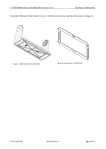
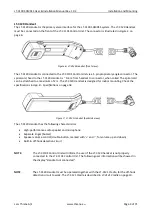
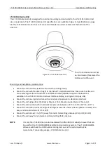
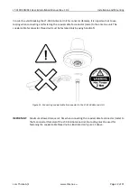
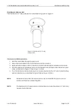
tube), Antenna Unit is illustrated in Figure 25 to Figure 27.
Pole mount installation procedure:
1.
Feed the coaxial cable through the pole mount
2.
Fasten the coaxial cable to the LT-3130 Antenna Unit (N connector)
3.
Apply self-volcanic tape on the N connector and cable to protect against saltwater and corrosion
4.
Screw the pole mount (clockwise) on the LT-3130 Antenna Unit, and fasten the antenna lock pinot
screw, as illustrated in Figure 27 (max torque = 1.2 Nm)
5.
The LT-
3130 Antenna Unit and pole mount can now be mounted on the 1.5”
tube. Fasten the three
pole lock pinot screws, as illustrated in Figure 26 (max torque = 4.5 Nm)
NOTE
:
Remember to fasten the antenna lock pinot screw (1.2 Nm) after the pole mount and
antenna unit have been screwed together.
NOTE
:
The Pole Mount
(1.5” tube), Antenna Unit interfaces to a tube of maximum 1.5” (38.1 mm),
measured outer diameter.
Figure 25:
Pole Mount (1.5”
tube),
Antenna Unit.


