


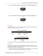


3: Installation of the PremierWave XC HSPA+ Device
PremierWave® XC HSPA+ Intelligent Gateway User Guide
26
2. Remove the paper clip to release the button. The unit will continue the boot process restoring
it back to the original factory default settings.
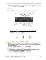
Back Panel
On the PremierWave device is a Power Connector and RJ-45 Ethernet port as shown in
Figure 3-11 PremierWave XC HSPA+ Bottom/Back Panel View
Table 3-12 PremierWave XC HSPA+ Connections (Side)
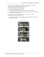
Installing the PremierWave XC HSPA+ Unit Device
Be sure to place or mount the device securely on a flat horizontal or vertical surface. The device
comes with brackets for mounting it, for example, on a wall. If using AC power, do not use outlets
controlled by a wall switch.
Observe the following guidelines when connecting the devices:
The PremierWave unit serial ports support RS-232/422/485.
Use a null modem cable to connect the serial port to another DTE device. Use a straight-
though (modem) cable to connect the serial port to a DCE device.
Connect your RJ-45 Ethernet cable to the RJ-45 port of the unit.
The PremierWave device supports a power range of 9 to 30 VDC.
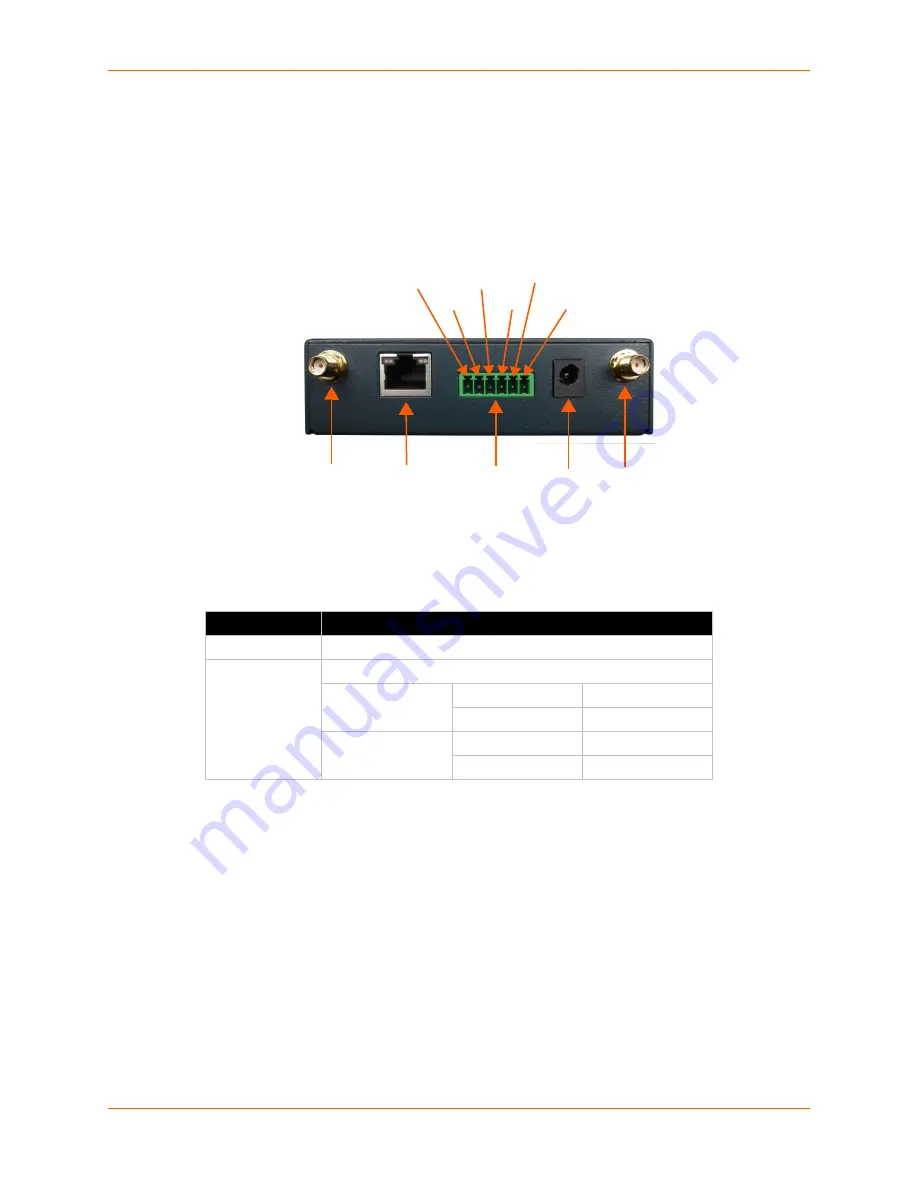
Connector
Description
Relay Output
Outputs Support 1A 24V
Inputs
Inputs accept voltage 0 to 30 VDC.
ON
Max
30 VDC
Min
2 VDC
OFF
Max
0.7 VDC
Min
0 VDC
Antenna Ethernet Terminal Block Locking Primary
(RX Diversity) Digital Input Barrel Antenna
Relay Output Connector
Power
Relay IN2 IN1
Relay CM2 CM1


