


Hardware Interfaces
BOLERO40 Series Hardware Manual
24
For example, if you want to use
IO2
as analogue and
IO3
and as digital, then use the
following commands respectively:
PFAL COMMANDS
IO INDEX DESCRIPTION
$PFAL,IO1.Config=AI,2,11
1
AI=analog; 2 and 11=min. and max. voltages for Low and
High events
$
PFAL,IO2
.
Config=DI,5,10
2
DI=digital input; 5 and 10=min. and max. voltages for Low
and High events.
If you want to use a digital pin, e.g.
IO2
or
IO3,
as a digital output pin, then use the following
PFAL command:
PFAL COMMANDS
IO INDEX DESCRIPTION
$PFAL,IO5.Set=high
5
AI=analog; 2 and 11=min. and max. voltages for Low and
High events
$PFAL,IO6.Set=cyclic,2000,1000
6
DI=digital input; 5 and 10=min. and max. voltages for Low
and High events.
In the sections below there are some examples showing how to use them.
When using IOs
as digital you must set them first to high (with PFAL command
“$PFAL,IO
5
.Set=high
” or “
$PFAL,IO
6
.Set=high
”), otherwise 0V will be
measured
and the device could get damaged.
6.1.1.1
How to use IOs as analogue inputs
When using IO as analogue inputs they have to be configured and calibrated with
corresponding PFAL commands. For more details, refer to the related documents
Analogue voltages of up to 32.0V with a 12 bits resolution can be processed and remotely
evaluated by a server application. A pull-up resistor to a constant input voltage allows for
resistive transducers to ground, e.g. fuel sensor or thermistors.
To use these IOs as analogue inputs, send the following command to the device.
PFAL COMMANDS
IO INDEX DESCRIPTION
$PFAL,IO
1
.Config=AI,2,11
1
Where
1
and
2
are indices corresponding to IO1 (yellow), IO2
(green), respectively. While the value 2 and 11 are min. and
max. voltages that will be used to generate Low and High
events, respectively. For more details, refer to the related
documents
$PFAL,IO
2
.Config=AI,2,11
2
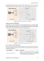
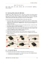
Connection example 1 (IO2 and IO3)
:
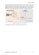
Analogue inputs can be connected to temperature sensors or tachometers (e.g. NTC
resistor as shown in Fig. 3 or Tachometer as shown in Fig. 3.1). Fig. 3 shows a fixed resistor
and a variable resistor (Negative Temperature Coefficient - whose resistance or capacitance
decreases when temperature increases) to ground. It is possible to set an alarm for low
temperatures and alarm for high temperature. Passage through these thresholds can
generate events that can be used to trigger alarms for low and high temperatures. Alarms