Lantronix 15.00.033 Product Manual Download Page 8

Lightwave Communications 


DVI Fiberlynx 

www.lightwavecom.com  

November 

2001 

8

2.3  DVI Cable Kits 

 
A six-foot-long 

DVI cable kit

 is included with the DVI Fiberlynx to connect the 

DVI Transmitter to your CPU. Use this kit at the CPU end. The cable kits include: 
one male-to-male TMDS (DVI-D connector) video cable, keyboard and mouse 
cables (varies per kit), one male-to-female DB9 serial cable, and two 3.5 mm 
audio cables. Eight rubber feet are also included to use the DVI Fiberlynx on a 
desktop, and 8 tie-wraps.  
 

2.4  Connecting the CPU to the Transmitter 

 
The following example uses and shows PS/2 connections. Other connector 
formats are similar.  
 
1. 

Place the CPU with the DVI Fiberlynx Transmitter.  

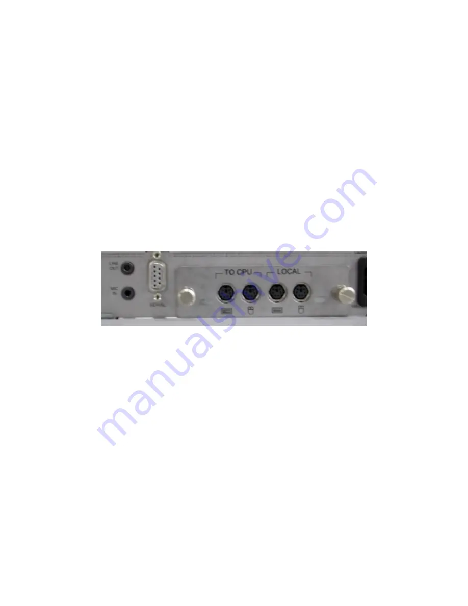
DVI Fiberlynx Transmitter: Audio, Serial and PS/2 Connections 

 
2.  

Install the Personality Module, if not already in place. The 

Transmitter 

Personality Module

 is used in the DVI Fiberlynx Transmitter. To install it, 

remove the Personality Module blank cover (two screws), slide the 
Transmitter Personality Module in, and secure it in place with its two 
screws (finger tight is adequate).  

 
3.  

Connect the keyboard and mouse ports from the CPU to the keyboard and 
mouse ports labeled "

TO CPU

" on the personality module in the DVI 

Fiberlynx transmitter. Use the PS/2 cables provided in the Cable Kit.  

 
4. 

Connect the CPU audio ports to the transmitter using the provided 3.5 mm 
stereo audio cables. The port marked “

MIC IN

” on the transmitter connects 

to the microphone port on the CPU, while the “

LINE OUT

” port on the 

transmitter connects to the speaker port on the CPU. 

 
5. 

Connect the CPU serial port to the transmitter 

SERIAL

 port (

DB9F

 on 

Transmitter chassis) using the provided male-to-female serial cable.  

Summary of Contents for 15.00.033

Page 1: ...DVI Fiberlynx PN 15 00 033 Product Manual November 2001 Revision B ...

Page 2: ... 9645 3377 Email sales lightwavecom com au Internet www lightwavecom com au LCI Europe Zaubzerstraβe 11 Munich D 81677 Germany 49 89 306 3810 Fax 49 89 306 3812 Email office lightwave de Internet www lightwave de VDI Fiberlynx User Manual LCI Part Number 15 00 033 Edition of November 14 2001 Revision B Copyright 2000 2001 Lightwave Communications Inc 100 Washington Street Milford CT 06460 USA All ...

Page 3: ...c Cable 6 2 3 DVI Cable Kits 8 2 4 Connecting the CPU to the Transmitter 8 2 4 Connecting the User Peripherals 10 3 0 Operation 12 3 1 Video Record 12 3 2 Video Resolution 12 3 3 Front Panel LEDs 12 Appendix A Serial Port Pinouts 15 Appendix B Specifications 16 B 1 Physical 16 B 2 Environmental 16 B 3 Electrical 16 B 4 Optical 16 B 5 Interface 17 B 6 Compliance and Certification 18 ...

Page 4: ...ansmitter and a Receiver The transmitter is located with the CPU while the receiver is located with the user peripherals keyboard mouse monitor etc The DVI Fiberlynx provides the following connections DVI D digital only Input from the Host CPU Local DVI D digital Video Output at CPU End Remote DVI D digital Video Output primary DVI output at User end Auxiliary DVI D digital Video Output identical ...

Page 5: ... 0 Installation Installation of the DVI Fiberlynx is simple and requires only simple hand tools Each Fiberlynx transmitter or receiver can be mounted in a standard 19 inch rack or may be placed on a bench or table The DVI Fiberlynx has been classified a CLASS 1 LASER Product in accordance with standards IEC 60825 1 and IEC 60825 2 Always operate the product in accordance with these instructions Do...

Page 6: ...hrough reflection off a shiny surface The LASER light can be harmful to your vision 4 Provide AC power connections for the DVI Fiberlynx units at each location as well as power for the CPU and any powered user peripherals such as a monitor and speakers The DVI Fiberlynx uses a universal power supply 2 2 Connecting Fiber Optic Cable 1 Install the Transmitter and Receiver units close to their final ...

Page 7: ...the provided strain relief device to prevent damage to the fiber optic cable Secure the fiber optic cable using a tie wrap or using the provided T nut and a clamp or both depending on what works best for your site Dress the cable so it will not be disturbed Rear of Transmitter unit showing suggested Fiber Optic routing 4 Avoid sharp bends or sharp corners The strain relief ties may be trimmed if d...

Page 8: ... 2 Connections 2 Install the Personality Module if not already in place The Transmitter Personality Module is used in the DVI Fiberlynx Transmitter To install it remove the Personality Module blank cover two screws slide the Transmitter Personality Module in and secure it in place with its two screws finger tight is adequate 3 Connect the keyboard and mouse ports from the CPU to the keyboard and m...

Page 9: ...uld light 8 Optional If using a local keyboard and mouse for testing or during setup you may connect a Keyboard and Mouse to the Transmitter s personality module s LOCAL connectors Connect your DVI monitor to the DVI OUT connector on the Transmitter Note The DDC video record must be established by the Video Source your CPU s video card before any video signal will be present To get the signal the ...

Page 10: ...er DVI and Fiber Optic Connectors Note During initial setup a DVI video configuration video record is made using the connection established between the CPU and the Monitor connected to the DVI OUT on the DVI Fiberlynx Receiver unit 3 Connect the audio devices to the Receiver The lower connector marked MIC IN is for use with a microphone only The upper connector marked LINE OUT is for connection to...

Page 11: ...nected and turned on before the signal will start If the signal is lost cable is unplugged etc the signal will be discontinued and will not recover the video source must be restarted This often means that your CPU must be restarted Power Up your equipment in this order after all wiring connections are done 1 Power Up your Monitor 2 Power Up the DVI Fiberlynx Receiver and Transmitter units 3 Power ...

Page 12: ... the signal reboot your CPU 3 1 Video Record During initial power up of the CPU a video record is established for the DVI monitor connected to your CPU The video record complies with VESA Display Data Channel DDC specification DDC2B The video record determines the operational characteristics of video output from the digital video interface If more than one monitor is connected the DVI Monitor conn...

Page 13: ...f normal solid red solid green adjusting coarse gain adjusting fine gain normal at start if constantly adjusting check fiber connection marked BLUE check fiber distance between stations check video source G off normal solid red solid green adjusting coarse gain adjusting fine gain normal at start if constantly adjusting check fiber connection marked GREEN check fiber distance between stations chec...

Page 14: ...left to right are Unit Receive and Unit Transmit Transmitter Unit label appearance status action RxD blinking green normal solid green unit not receiving data check fiber connections cycle power TxD blinking green normal solid red or orange not transmitting data check fiber connections cycle power on both units ...

Page 15: ...r Receiver Serial Connector 1 Data Carrier Detect DCD 2 Receive Data RxD 3 Transmit Data TxD 4 Data Terminal Ready DTR 5 Signal Ground GND 6 Data Set Ready DSR 7 Ready To Send RTS 8 Clear To Send CTS 9 Ring Indicator RI 1 4 6 8 7 2 3 5 Tx Rx RTS CTS DTR DSR DCD SG Serial Output RS 232 9 RI DB9M 1 4 6 8 7 2 3 5 Tx Rx RTS CTS DTR DSR DCD SG Serial Input RS 232 RI 9 DB9F CPU Side Desktop Side ...

Page 16: ...o 90 RH non condensing Storage temperature 4 F 20 C to 161 F 70 C Storage humidity 10 to 90 RH non condensing B 3 Electrical Input Requirements Universal AC input auto switching IEC Cordset provided 100 240 VAC 50 60 Hz 0 5A B 4 Optical B 4 1 LASERs and Detectors Note The DVI Fiberlynx is a CLASS 1 LASER PRODUCT Wavelength 840 nm Pulse Duration 6 35 39 72 nS Max Output Power 0 237 mW Loss budget 7...

Page 17: ... B 5 2 Keyboard and Mouse PS 2 Personality Module Transmitter Connector Four 6 pin mini DIN PS 2 Keyboard In Mouse In Local Keyboard Out Local Mouse Out Receiver Connector Two 6 pin mini DIN PS 2 Keyboard Out Mouse Out Format PS 2 Arrangement Keyboard and Mouse Note Other Personality Module formats also available B 5 3 Serial Transmitter Connector DB9 female Receiver Connector DB9 male Specificati...

Page 18: ...ECEE CB Scheme National Certification Body NCB Certification Body Testing Laboratory CBTL CE certification Conforms to FCC part 15 Class A Note This equipment has been tested and found to comply with the limits for a Class A digital device pursuant to Part 15 of the FCC Rules The limits are designed to provide a reasonable protection against harmful interference when the equipment is operated in a...

Reviews: