30
The system provides six externally accessible disk drive bays on the front panel. Notably, the system requires
2.5” SATA HDD/SSD. Please follow the steps below to install or replace disk drives.
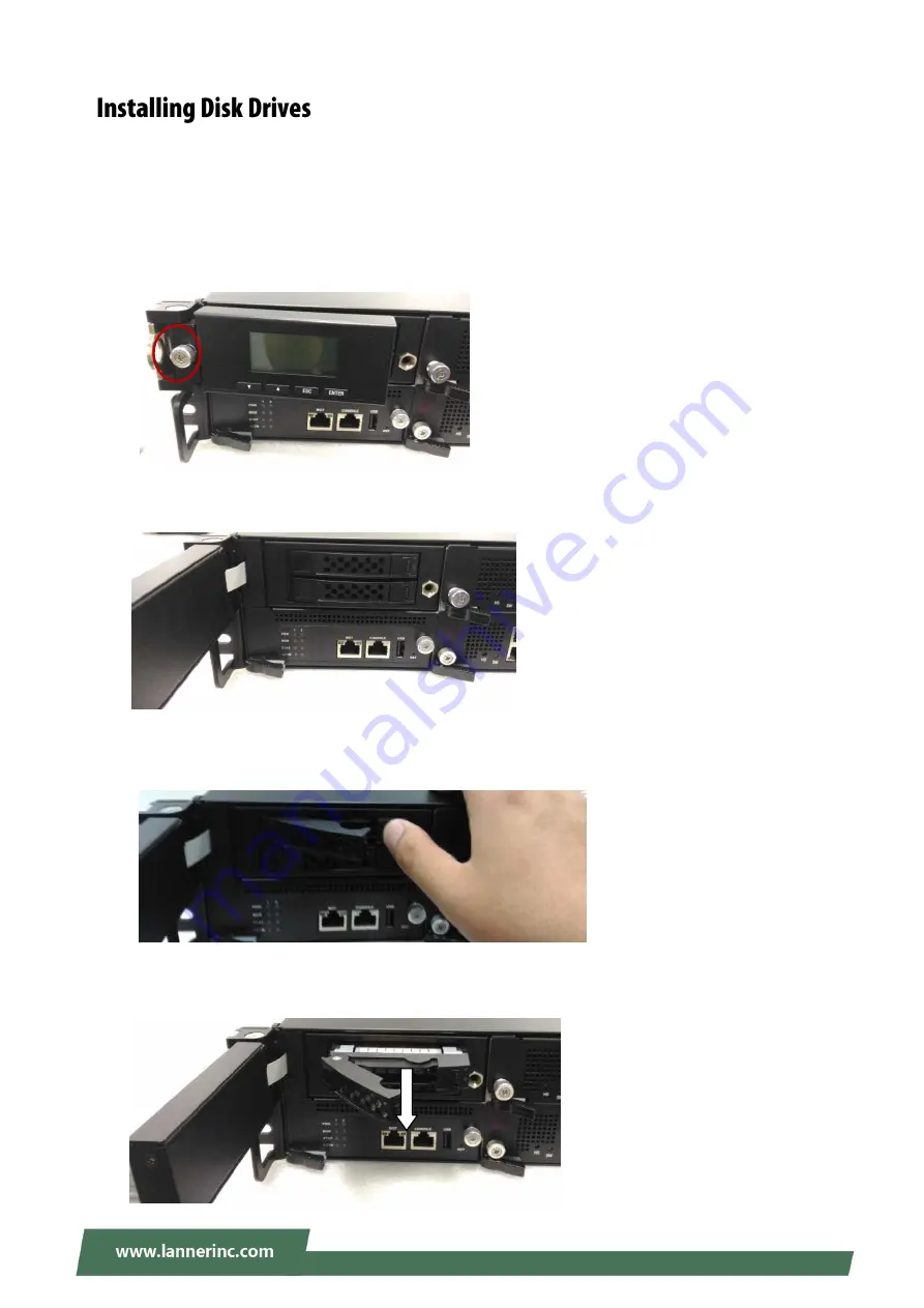
1.
The two 2.5” SATA disk drives are located behind the hinge LCM. Rotate and loosen the
lock-screw.
2.
Open the hinge LCM and locate the HDD/SSD bays as the images shown below.
3.
Select a drive bay for installation and hold the lock of the drive bay.
4.
Open the lock outwards.
5.
Pull the drive bay out and install a 2.5” SATA disk drive. Please keep in mind that the SATA connector of
your SATA disk drive should point to the inside of the system.
Summary of Contents for HTCA-6200
Page 9: ...HTCA 6200_user manual 9 ...
Page 12: ...HTCA 6200_user manual 12 ...
Page 20: ...20 OPMA1 OPMA socket for IPMI card ...
Page 23: ...23 CONN3 HS pin header Pin Description 1 HSWAP_ENABLE_N 2 GROUND ...
Page 39: ...39 HW Monitor This option allows you to view hardware health status ...
Page 50: ...50 mSATA enable or disable the mSATA port ...
Page 51: ...SATA1 enable or disable the SATA1 port 51 SATA2 enable or disable the SATA2 port ...
Page 52: ...52 SATA3 enable or disable the SATA3port SATA4 enable or disable the SATA4port ...
Page 54: ...54 You may select Enabled Disabled or Auto ...
Page 57: ...57 Memory Configuration ...
Page 60: ...60 ...
Page 68: ...68 Discard Changes and Exit exit system setup without saving the configuration changes ...
Page 69: ...69 Restore Defaults restore load factory default setting for all setup parameters ...
Page 70: ...70 Boot Override You may select a device under Boot Override for this function ...
Page 71: ...71 ...
Page 81: ......


