


3
Introduction
Chapter 1
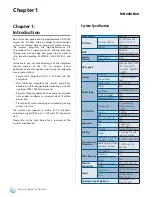
Network Application Platforms
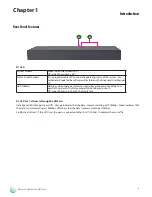
Front Panel Features
F2
F1
F6
F1 ATX Power Switch
A system power switch.
F2 DC-12V
DC-in connector for connecting DC power source (60W). Use only the power adaptor included within the package.
F3 LED
System (Green)
Green: when the system is on.
Off: when the system is off.
Status (Green/Amber)
It is a programmable LED to show the operating status of the system. For
more details, look for the software utility folder in the Driver and User Manual
CD.
Hdd (Yellow)
Flashing: when there are data access activities or when the CompactFlash
card or SATA disk (on model FW-6436B only) is present or both
Off: when there is no CF or SATA disk present..
F4 Reset Switch
A hardware (default) or a software reset switch. You will need to set it to either hardware or software reset in the BIOS.
F5 Console Port
It is a console port via RJ45 connector. Using suitable RS-232 cable, you can connect an appropriate device, for example,
a terminal console for diagnostics.
Terminal Configuration Parameters: 115200 baud, 8 data bits, no parity, 1 stop bit , no flow control.
F6
4 10/100/1000 Gigabit Ethernet Ports
The Gigabit Ethernet ports are provided by Realtek RTL8111E-GR Integrated 10/100/1000 Ultra Gigabit Ethernet
Transceiver through the PCI-e interface. They support both Wake-on-LAN and remote wake-up. They also support the
IEEE 802 IP Layer 2 priority encoding and IEEE 802.1Q VLAN tagging.
LED Indicator
LED Function
LED Color
On
Off
Blinking
Left
Link/Activity
Yellow
connected
Not connected Linking/there is
traffic
Right
Data Speed
Green
Orange
100 Mbps
1000 Mbps
10 Mbps
F7 USB 2.0 Ports
It connects to any USB devices, for example, a flash drive. Besides this external USB port, there is another one with the
internal pin headers (refer to
Jumper Setting
on
Chapter 3 Motherboard Information
)
F8 PCI Expansion Slot
In addition to these two PCI expansion slots, there is also one internal Mini-PCI connector .
F3
F4
F5
F7