Lanner FW-6436 User Manual Download Page 18

15

Terms and  Conditions

Appendix A

Embedded and Industrial Computing

Appendix A:  

Terms and Conditions

Warranty Policy 

  All  products  are  under  warranty  against  defects  in 

1. 

materials  and  workmanship  for  a  period  of  one  year 

from the date of purchase.
The  buyer  will  bear  the  return  freight  charges  for 

2. 

goods returned for repair within the warranty period; 

whereas the manufacturer will bear the after service 

freight charges for goods returned to the user.
The buyer will pay for repair (for replaced components 

3. 

plus  service  time)  and  transportation  charges  (both 

ways)  for  items  after  the  expiration  of  the  warranty 

period.
 If the RMA Service Request Form does not meet the 

4. 

stated  requirement  as  listed  on “RMA  Service,”  RMA 

goods will be returned at customer’s expense.
The  following  conditions  are  excluded  from  this 

5. 

warranty:

Improper  or  inadequate  maintenance  by  the  customer 

Unauthorized  modification,  misuse,  or  reversed 

engineering  of  the  product  Operation  outside  of  the 

environmental specifications for the product.
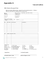
RMA Service 

Requesting a RMA#

 To obtain a RMA number, simply fill out and fax the 

6. 

“RMA Request Form” to your supplier.
The customer is required to fill out the problem code 

7. 

as listed. If your problem is not among the codes listed, 

please write the symptom description in the remarks 

box. 
  Ship  the  defective  unit(s)  on  freight  prepaid  terms. 

8. 

Use the original packing materials when possible.
 Mark the RMA# clearly on the box. 

9. 

Note:

  Customer  is  responsible  for  shipping 

damage(s)  resulting  from  inadequate/loose 

packing of the defective unit(s). All RMA# are valid 

for  30  days  only;  RMA  goods  received  after  the 

effective RMA# period will be rejected.

Summary of Contents for FW-6436

Page 1: ...Network Application Platforms Hardware platforms for next generation networking infrastructure FW 6436 User s Manual Publication date 2012 05 15 Version 2 0...

Page 2: ...inal manufacturer assumes no responsibility for its use nor for any infringements upon the rights of third parties that may result from such use Acknowledgement Intel Pentium and Celeron are registere...

Page 3: ...ng a CompactFlash Card 6 Chapter 3 Mechanical Dimensions 7 System Mechanical Dimensions 7 Chapter 4 Motherboard Information 8 Block Diagram 8 Motherboard Layout 9 Jumper Settings 10 Appendix E Driver...

Page 4: ...slots Please refer to the chart below for a summary of the system s specifications System Specification Form Factor Desktop Platform Processor Options VIA ULV Eden 500 MHz or VIA C7 1 5 GHz Chipset VI...

Page 5: ...ge Contents Your package contains the following items FW 6436 Network Security Platform Power cable 1 crossover Ethernet cable 1 8 meters 1 straight through Ethernet cable 1 8 meters 1 RJ45 to DB 9 co...

Page 6: ...ctor Using suitable RS 232 cable you can connect an appropriate device for example a terminal console for diagnostics Terminal Configuration Parameters 115200 baud 8 data bits no parity 1 stop bit no...

Page 7: ...Flashing when there are data access activities or the presence of the Com pactFlash card or SATA disk on model FW 6436B only or both Off when there is no CF or SATA disk present R2 LED for 1 4 from le...

Page 8: ...two screws 2 on the back of the top cover of the FW 6436 System Slide the cover backwards to open it 3 Installing the Hard Disk The system can accommodate one Serial ATA disk 2 5 or 3 5 Follow these s...

Page 9: ...ts DDR2 memory that features data transfer rates of 800 or 1066 MHz to meet the higher bandwidth requirements of the latest operating system and Internet applications It comes with one Double Data Rat...

Page 10: ...7 Mechanical Dimensions Chapter 3 Network Application Platforms Chapter 3 Mechanical Dimensions System Mechanical Dimensions...

Page 11: ...board s layout design VIA Eden ULV 500MHz 1 5GHz VIA VX900 LPC FSB 400 533 800 1066MHz 4x GbE RJ 45 4x PCI E x1 Compact Flash 2x pin headers USB 2 0 DDR3 SO DIMM Slot Realtek 8111E Winbond 83627DHG SP...

Page 12: ...internal connectors U S B C o n n e c t o r USB1 LANB1 LANB2 LANB3 LANB4 VGA Connector VGAB1 RJ45 Console Port Software or Hardware Reset Button sw_rst_btn1 Clear CMOS Jumper CMOS1 CompactFlash Connec...

Page 13: ...DATA0 46 DIAG 22 DATA1 47 DATA8 23 DATA2 48 DATA9 24 WP 49 DATA10 25 CD2 50 GND Jumper Settings CMOS Jumper CMOS1 It is for clearing the CMOS memory and system setup parameters by erasing the data sto...

Page 14: ...AD17 58 AD18 59 C_BE 2 60 AD16 61 IRDY 62 GROUND 63 3 3V 64 FRAME 65 CLKRUN 66 TRDY 67 SERR 68 STOP 69 GROUND 70 3 3V 71 PERR 72 DEVSEL 73 C_BE 1 74 GROUND 75 AD14 76 AD15 77 GROUND 78 AD13 79 AD12 80...

Page 15: ...e key capabilities are listed below Integrated 10 100 1000 transceiver Auto Negotiation with Next Page capability Supports PCI Express 1 1 Supports pair swap polarity skew correction Crossover Detecti...

Page 16: ...then log on with 1 Administrator privileges Insert the Drivers and User s Manual CD to the USB 2 Optical drive Browse the contents of the Drivers and User s Manual 3 CD to locate the file SETUP EXE f...

Page 17: ...on other operating systems visit Realtek s download page at http www realtek com tw Downloads downloadsView aspx Langid 1 PNid 13 PFid 5 Level 5 Conn 4 DownTypeID 3 GetDown fa lse Chipset Platform Dr...

Page 18: ...ll be returned at customer s expense The following conditions are excluded from this 5 warranty Improper or inadequate maintenance by the customer Unauthorized modification misuse or reversed engineer...

Page 19: ...ing by Air Freight Sea Express ___ Others ________________ Item Model Name Serial Number Configuration Item Problem Code Failure Status Problem Code 01 D O A 02 Second Time R M A 03 CMOS Data Lost 04...

Reviews: