


7
❏
5. Thread a nylon clevis onto each of the two 6" [152mm]
pushrods 20 complete turns. Slide a silicone clevis retainer
onto the base of each clevis.
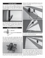
Hinge Line
Hinge Line
CORRECT
INCORRECT
Hi
❏
6. Attach a clevis to the outer hole of a large control
horn. Position the control horn onto the aileron, aligning the
pushrod with the second inner hole of the aileron servo arm.
Position the control horn over the plywood plate in the aileron
(if you cannot see it, hold the aileron at a shallow angle in
good lighting or use a small pin to puncture the covering).
When satisfi ed, use a felt-tip pen to mark the location of the
control horn mounting holes onto the aileron. Repeat this
step for the other wing panel.
❏
7. Drill 5/64" [2mm]
holes at the marks you
made. Install the control
horns onto the ailerons
using 2-56 x 5/8" [16mm]
machine screws and
control horn backplates.
❏
8. With the ailerons in the neutral position (use tape or
small clamps to hold them in place) and the servos centered,
mark the pushrod wires where they cross the second inner
holes in the servo arms.
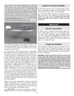
Servo Horn
1/16"
2-56 (.074")
Pushrod Wire
FasLink
❏
9. Make a 90° bend at the mark on each pushrod and cut
off the excess pushrod 1/4" [6mm] beyond the bends. Attach
the pushrods to the servo arms using nylon FasLinks. Thread
the clevises up or down on the pushrods as necessary to
center the ailerons with the servo arms still perpendicular
to the servo cases. When satisfi ed, slide the silicone clevis
retainers to the ends of the clevises to secure them.
❏
10. Attach a 6" [152mm] servo extension to each aileron
servo. Secure the connections using the included pieces of
heat shrink tubing. A heat gun, hair dryer or lighter can be
used to shrink the tubing onto the connections.
Summary of Contents for MARINER 40 MK II ARF
Page 24: ......


