background image

MAINTENANCE

9K998                                                                                                                                                                          4-5

Hydraulic Maintenance

IMPORTANT

Lower the unit to the ground, and relieve hydraulic 
pressure before attempting to service any hydraulic 
component.

WARNING

1. Check the tractor hydraulic fluid level per Tractor 

owner's manual and after any leakage. Check fluid 
level with the Hydraulic Cylinders in the extended 
position.

2. If a Hydraulic Cylinder leaks, disassemble the parts 

to determine the cause of the leak. Any time a 
Hydraulic Cylinder is opened up, or whenever any 
Seal replacement is necessary, it is advisable to 
clean all parts and replace all Seals. Seal Kits are 
available from your Brillion dealer.

3. Check all Hydraulic Hoses weekly. Look for binding 

or cracking. Replace all worn or defective parts 
immediately.

4. Transport Locks are provided to hold the implement 

in a raised position. Do not attempt to perform any 
service work under the implement without first 
installing the Transport Locks.

 Figure 3-5. 

Before 

servicing any hydraulic component, lower the 
implement to the ground and relieve all system 
pressure. If a hydraulic component is disconnected, 
repaired, or replaced, it will be necessary to purge 
the system of air before operation. 

See “Hydraulic 

Lift System” on page 3-7.

Front and Rear Rollers

After an initial run of 5-10 hours, check the Front and 
Rear Roller Assemblies to ensure that the Wheels are 
tight to one another and that the Clamp Bands are tight. If 
not slide the Roller Wheels tight together and adjust the 
Roller Clamp Bands. Tighten the Clamp Band Socket 
Head Bolt (Clamp Band open section) over Roller Drum 
weld seam to 75ft-lbs. Thereafter check Front and Rear 
Roller Assemblies every 50-100 hours.

IMPORTANT

To maximize seed germination, peaks on Rear Roller 
Wheels should line up with valleys on the Front 
Roller Wheels. This will require adjusting the Clamp 
Bands on each end of the Rear Roller Drum and 
moving the Wheels until valleys and peaks line up. 
Turfmaker Sprockets may be added between the 
Rear Roller Wheels to improve the alignment of the 
peaks and valleys. Add as many Turfmaker 
Sprockets between the Wheels as required to 
achieve proper alignment. Each Sprocket is 3/8” 
wide. Figure 2-56.

NOTE

Failure to position the Clamp Band Socket Head Bolt 
(Clamp Band open section) over the Roller Drum weld 
seam will cause Clamp Band to loosen and slide.

Roller Adjustment Procedure

1. Adjust the Front Roller Wheels first. Loosen Clamp 

Bands and slide the Roller Wheels snug against 
each other, centering the entire assembly under the 
Deflector. 

2. Position the Clamp Band Socket Head Bolt (Clamp 

Band open section) over the weld seam on the Roller 
Drum. 

3. Slide the Clamp Band against the End Wheel on 

each end of the Roller and tighten the Clamp Band 
Bolt to 75ft-lbs.

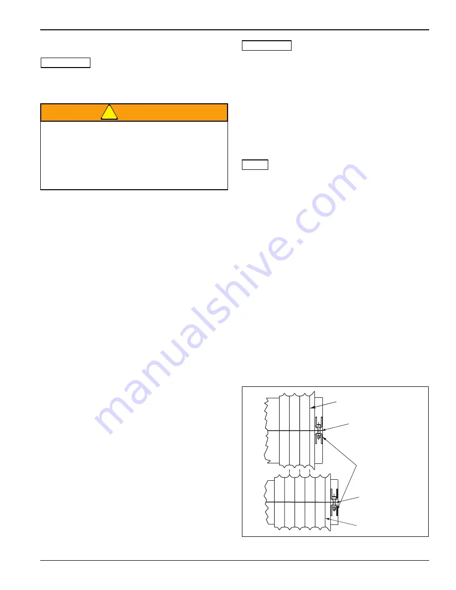
 Figure 4-3.

Adjust the Rear Roller Wheels in the same manner as 
you adjusted the Front Roller Wheels except, start at the 
center of the Rear Roller and align the peaks of the Rear 
Roller Wheels with the valleys of the Front Roller Wheels. 
This will provide the best alignment of worn Roller 
Wheels.

Figure 4-3:  Clamp Bands

Escaping fluid under pressure can be nearly 
invisible and have enough force to penetrate the 
skin causing serious injury. Use a piece of 
cardboard, rather than hands to search for 
suspected leaks. Wear protective gloves and 
safety glasses or goggles when working with 
Hydraulic System

5HDU5ROOHU

)URQW 5ROOHU

&ODPS%DQGV

:HOGHG6HDP

:HOGHG6HDP

Summary of Contents for BRILLION TURFMAKER II SL

Page 1: ...9K997 0120 01 2020 Present LANDOLL CORPORATION 1900 North Street Marysville Kansas 66508 785 562 5381 800 428 5655 WWW LANDOLL COM TURFMAKER II Models SL SLB SLP SLPB 8 10 and 12 Operator s Manual...

Page 2: ......

Page 3: ...s 1 3 Tire Safety 1 3 Safety Chain 1 4 2 Assembly 3Pt Seeder Assembly 2 2 Pull Type Seeder Assembly 8Ft and 10Ft 2 4 Tire and Wheel Installation 2 5 Hydraulics 8Ft and 10Ft 2 6 Purge the Hydraulic Lif...

Page 4: ...nge 11 to 22 Tooth 3 14 Acre Meter Optional 3 16 Settings for Loup Acre Meters After 05 15 2012 3 16 Field Acres 3 16 Total Acres 3 16 Pulses Per 400 Feet 3 16 Width 3 16 Password 3 16 Changing the Pa...

Page 5: ...n 4 6 Transmission 01 2020 and After 4 6 Transmission 01 2020 and Prior 4 7 Seed Meter Adjustment 4 8 LED Warning Lamps 4 10 Acre Meter Troubleshooting 4 11 Storage 4 11 5 General Reference Tables and...

Page 6: ...iv...

Page 7: ...t specially designed for Brillion products Your machine s parts should only be replaced with Brillion parts If items covered in this manual are not understood contact your local Brillion Dealer Warran...

Page 8: ...adequate warning symbols reflectors lights and slow moving vehicle sign purchased separately as required Slow moving tractors and towed implements can create a hazard when driven on public roads They...

Page 9: ...o search for suspected leaks Any fluid injected into the skin must be surgically removed within a few hours or gangrene may result Avoid the hazard by relieving pressure before disconnecting hydraulic...

Page 10: ...ement 3 Attach the chain to the Tractor Drawbar Support or specified anchor location Never attach the chain to an intermediate support Allow only enough slack in the chain to permit turning The distan...

Page 11: ...UNLISTED SEED AS FOLLOWS 1 RAISE MACHINE AND LOCK IN TRANSPORT POSITION 2 DISENGAGE CLUTCH ELECTRICAL POWER IS REQUIRED TO DISENGAGE 3 IF EQUIPPED CLOSE METERS OF REAR SEED BOX IF CONTAINS SEED 4 PLAC...

Page 12: ...1 6 9K998 INTRODUCTION AND SAFETY INFORMATION Figure 1 4 Safety Signs 2 of 5 6 HFDOV6LQJOH R IW...

Page 13: ...INTRODUCTION AND SAFETY INFORMATION 9K998 1 7 Figure 1 5 Safety Signs 3 of 5 6 HFDOV6LQJOH R IW...

Page 14: ...1 8 9K998 INTRODUCTION AND SAFETY INFORMATION Figure 1 6 Safety Signs 4 of 5 6 HFDOV RXEOH R...

Page 15: ...INTRODUCTION AND SAFETY INFORMATION 9K998 1 9 Figure 1 7 Safety Signs 5 of 5 6 LWFK HFDOV...

Page 16: ...1 10 9K998 INTRODUCTION AND SAFETY INFORMATION Table provided for general use NOTES...

Page 17: ...all working parts move freely bolts are tight and cotter pins spread Refer to the Torque Table for proper torque valves Note the different torque requirements for bolts with lock nuts See Page 4 1 Le...

Page 18: ...eed Box Center Bracket with 3 8 16 x 1 1 2 Bolts Flat Washers Lock Washers and Nuts See Figure 2 1 Figure 2 1 SMV Support CAUTION 5 Be sure Parking Pin is locking Rear Roller down and raise the Seeder...

Page 19: ...ASSEMBLY 9K998 2 3 Figure 2 4 3Pt Hitch RVH ODPS 0DQXDO ROGHU 3W LWFK 1XW RFN DVKHU 8 ROW UDPH 6 2S 3W LWFK...

Page 20: ...nter Bracket Attach Drawbar to Seeder Frame Tube with 5 8 11 U Bolts Lock Washers and Nuts See Figure 2 6 3 Attach the Hose Holder to the Drawbar with 5 8 11 x 1 1 2 Bolt Lock Washer and Nut 4 Install...

Page 21: ...erval and re tighten them 8Ft Seeder uses 9 5L x 15 8Ply Implement Rib Rating Tires and should be inflated to 44 PSI 10Ft Seeder uses 11L x 15 12Ply Implement Rib Rating Tires and should be inflated t...

Page 22: ...are free to swivel Connect top Hydraulic Hose to the Cylinder Base and bottom Hydraulic Hose to the Cylinder Rod End Position the Hydraulic Hoses so that the Cylinder Base End points downward and the...

Page 23: ...ASSEMBLY 9K998 2 7 Figure 2 11 8Ft and 10Ft Drawbar Hydraulics ROW 7RS 3ODWH UDZEDU RVH ODPS 3DLU RVH VVHPEO UDPH 2S 6HHGHU G...

Page 24: ...der to verify that both Cylinders are working throughout the stroke Fully extend the Lift Cylinders and continue to hold the lever until both Cylinder Rod movement stops Raise Lower Seeder 5 times to...

Page 25: ...ASSEMBLY 9K998 2 9 Table provided for general use NOTES...

Page 26: ...r Frame Tube 2 Center Drawbar in relationship with the Seed Box Center Bracket Attach Drawbar to Seeder Frame Tube with 5 8 11 U Bolts Lock Washers and Nuts Align Braces with the front of the Seeder F...

Page 27: ...ts for proper torque after this interval and re tighten them 1 12Ft Seeder uses 11L x 15 12Ply Implement Rib Rating Tires and should be inflated to 52 PSI 2 Install a Tire and Wheel Assembly onto each...

Page 28: ...are free to swivel Connect top Hydraulic Hose to the Cylinder Base and bottom Hydraulic Hose to the Cylinder Rod End Position the Hydraulic Hoses so that the Cylinder Base End points downward and the...

Page 29: ...ASSEMBLY 9K998 2 13 Figure 2 19 12Ft Drawbar Hydraulics RVH ODPS 3DLU 7RS 3ODWH ROW RVH VVHPEO UDZEDU UDPH 2S 6HHGHU G IW...

Page 30: ...ise the Seeder to verify that both Cylinders are working throughout the stroke Fully extend the Lift Cylinders and continue to hold the lever until both Cylinder Rod movement stops Raise Lower Seeder...

Page 31: ...ASSEMBLY 9K998 2 15 Table provided for general use NOTES...

Page 32: ...Lamp 6 Repeat for the Left Side Yellow Tape 7 Plug the 7 Pin Harness into the Light Module then route the Harness along the Drawbar with the Hydraulic Hoses and secure with Tie Wraps 8 Bundle and sec...

Page 33: ...DPS DUQHVV 3LQ DUQHVV 609 ODW DVKHU ROW RFNQXW 609 6XSSRUW RFNQXW ROW PEHU DPS 5HG DPS LJKW UDFNHW 7LH UDS 0RXQWLQJ 3ODWH 5HG DPS ROW PEHU DPS LJKW UDFNHW LJKW 0RGXOH ROW 7LH 6WUDS DPS DUQHVV 3LQ DUQ...

Page 34: ...Plug the 7 Pin Harness into the Light Module then route the Harness along the 3Pt Hitch 8 Bundle and secure excess cord to the Module Bracket with Tie Wraps Secure cords along frame and 3Pt Hitch usi...

Page 35: ...nstallation 12Ft 609 ROW ODW DVKHU RFNQXW LJKW DU DPS DUQHVV 3LQ DUQHVV 7LH UDS 0RXQWLQJ 3ODWH ROW PEHU DPS ROW DPS DUQHVV 7LH UDS LJKW 0RGXOH ODW DVKHU RFNQXW ROW RQQHFWRU ROGHU ROW PEHU DPS RFNQXW R...

Page 36: ...2 20 9K998 ASSEMBLY Table provided for general use NOTES...

Page 37: ...l make a clicking sound Set Seeder on the ground and drive a short distance while turning Toggle Switch to Seed and No Seed The Seed Shaft will stop rotating when Toggle Switch is turned to No Seed Po...

Page 38: ...ick up Switch See Figure 2 28 6 Adjust the Pick up Switch and Pick up Switch Mount so the centerline of the Magnet Wheel Assembly and Pick up Switch are horizontally and vertically aligned with maximu...

Page 39: ...W DVKHU RFN DVKHU ROW FUH 0HWHU VVHPEO 0DJQHW KHHO VVHPEO RFN DVKHU 1XW 1XW 1XW RFN DVKHU 6FUHZ 6FUHZ ODW DVKHU 6FUHZ 3LFN 8S 6ZLWFK 0RXQW 3LFN 8S 6ZLWFK FUH 0HWHU 0RXQW GKHVLYH 0RXQWLQJ 3ODWH 7LH UDS...

Page 40: ...e Magnet Wheel Assembly and remove the 1 4 20 hardware 6 Insert Seed Shaft Sensor into Shaft Sensor Bracket Slot See Figure 2 31 7 Align the Shaft Sensor Bracket with the two 1 4 20 Bolts Secure with...

Page 41: ...ASSEMBLY 9K998 2 25 Figure 2 32 Seed Shaft Sensor Mounting Dimensions Seedmeter 5HWDLQLQJ 1XWV 0D 0DJQHW KHHO VVHPEO 6KDIW 6HQVRU UDFNHW 6HHG 6KDIW 6HQVRU 0DJQHW 6HHG6KDIW6HQVRU LP...

Page 42: ...labeled Electric Clutch Power to the Electric Clutch Lead See Figure 2 33 8 Connect plug labeled Left Front Seed Shaft Sensor to the left front Seed Shaft Sensor Seal the plug end using a 3 Pin Tower...

Page 43: ...d to it from the Seed Box RH Support and Seed Rate Adjusting Screw 8 At the center of the Seeder where the RH and LH Hex Seed Shafts come together remove Seed Shaft Coupling and unscrew RH Seed Shaft...

Page 44: ...ket onto Sprocket Cover Weldment Channel with 5 8 11 X 2 1 4 Bolt Flat Washers 5 8 x 1 x 14ga Washers Lock Washer and Nut Do not tighten at this time Mount Sprocket Cover Weldment on Transmission whil...

Page 45: ...X 1 3 4 Bolts and a 3 8 16 x 1 1 2 Bolt Flat Washers and Lock Washers and Nuts Do not tighten at this time 22 Assemble RH Double Box Support onto RH Front Seed Box with Hardware but do not tighten at...

Page 46: ...and tighten Jam Nuts against Feed Roll Coupler 33 On the side of the Transmission by the Electric Clutch position the Idler Sprocket so that it applies tension to the 40 Drive Chain Tighten the Idler...

Page 47: ...emove Seed Rate Adjuster Bearing Carrier Plate with Bearing still Assembled to it from the Seed Box RH Support and Seed Rate Adjusting Screw 8 At the center of the Seeder where the RH and LH Hex Seed...

Page 48: ...Center Bracket against LH Front and LH Rear Seed Boxes 15 While supporting the RH Front Seed Box position Seed Box against Double Box Center Bracket Assemble Seed Boxes and Center Bracket together wit...

Page 49: ...justing Nut and 1 2 13 Locknut Place Bearing between Flangettes and attach to Bearing Carrier with 5 16 18 x 1 Bolts Lock Washers and Nuts See Figures 2 49 and 2 50 Figure 2 49 Rear Box Seed Rate Adju...

Page 50: ...Y Figure 2 50 Rear Box RH End Assembly ODW DVKHU RFN DVKHU 1XW ROW HDULQJ DUULHU 1XW 5 6HHG 6KDIW RFNQXW 6HHG 5DWH GMXVWLQJ 1XW GMXVWLQJ 6FUHZ ROW HDULQJ ODQJHWWH 5 RXEOH R 6XSSRUW 1XW RFN DVKHU 6 2S5...

Page 51: ...ackets to the Brackets with 1 2 13 x 3 1 4 x 4 9 16 U Bolts Lock Washers and Nuts Do Not tighten at this time 3 Attach the Scraper Angle to the LH and RH Angle Brackets with 1 2 13 x 1 1 4 Bolts Flat...

Page 52: ...ptional QJOH UDFNHW 6HHGHU UDPH 7XEH HQWHU 6FUDSHU 6FUDSHU ODW DVKHU RFN DVKHU 1XW DUULDJH ROW 6FUDSHU QJOH QJOH UDFNHW 8 ROW UDFNHW 8 ROW RFN DVKHU 1XW ODW DVKHU RFN DVKHU 1XW ROW 5 QJOH UDFNHW 6FUDS...

Page 53: ...ooth Tube with Straps 1 2 13 x 6 Bolts Lock Washers and Nuts See Figure 2 53 3 Center Tooth Tube in relationship with the Drawbar or 3Pt Hitch and Tighten U Bolts 4 Attach the S Tines onto the Tooth T...

Page 54: ...S Tine Track Remover Kit Optional 6HHGHU UDPH 7XEH 8 ROW RFN DVKHU 1XW 6 7LQH UDFNHW DUULDJH ROW 7RRWK 7XEH ODQJH RFNQXW XFN RRW 3RLQW 5HYHUVLEOH 3RLQW 3ORZ ROW 1XW RFN DVKHU 6 7LQH RFNQXW 6WUDS ROW O...

Page 55: ...nt to the Adjusting Angles with 1 2 13 x 1 3 4 Bolts and Locknuts Tighten the Locknuts to allow free side to side swinging 7 Center each Coil Tine Track Remover Assemble behind the Tractor Tires Tight...

Page 56: ...N DVKHU UDFNHW ROW ROW RFNQXW UP HOGPHQW ODW DVKHU RFN DVKHU 1XW RLO 7LQH 5RXQG DU ROW RFN 6FUHZ GMXVWLQJ QJOH 6HHGHU UDPH 7XEH ODW DVKHU RFN DVKHU 1XW ROW GMXVWLQJ QJOH KDLQ DLU 3LQ RWWHU OHYLV 3LQ R...

Page 57: ...el onto the Drum Pipe next to the last Wheel Spacer 3 Slide the Clamp Band over the Drum Pipe and next to the Half Wheel Position the Clamp Band Socket Head Bolt Clamp Band open section over the weld...

Page 58: ...2 42 9K998 ASSEMBLY Table provided for general use NOTES...

Page 59: ...lure to do so can result in serious injury or death and cause damage to the equipment When transporting the unit place cylinder lockouts in the transport lock position after fully extending the cylind...

Page 60: ...in a poor germination 5 Set Lift Rod length long enough to ensure Seeder can float downward in the case of a furrow or waterway Lower Links should be the same height leveling your Brillion Seeder side...

Page 61: ...OPERATION 9K998 3 3 Figure 3 1 3 Point Hitch DWHJRU UHH LQN 3LQ 3LQ DWHJRU 1DUURZ 4XLFN RXSOHU 3LQ 3LQ XVKLQJ XVKLQJ DWHJRU 4XLFN RXSOHU 3LQ 3LQ XVKLQJ XVKLQJ 2S DUJH6HHGHU 3W LWFK...

Page 62: ...r 1 With Seeder raised remove the Klik Pin push in the Parking Pin replace the KIik Pin See Figures 3 2 and 3 4 2 Disconnect the Tractor from Seeder lower Seeder Figure 3 3 Parking Pin Disengaged Figu...

Page 63: ...he safety chain should latch securely to prevent it from coming loose See Figure 3 6 Figure 3 6 Safety Chain 6 Plug the 7 Pin Connector to Tractor Outlet routing cable by avoiding pinch points Make su...

Page 64: ...ort Locks in the engaged position over the Cylinder Rod Secure with the Clevis Pins and Hairpin Cotters See Figure 3 5 4 Transport the Seeder to the area to be seeded 5 Disengage each Transport Lock s...

Page 65: ...or air to clean the Electric Clutch as damage could occur The Electric Clutch is controlled by a Toggle Switch on the Clutch Switch Box that is mounted to the Tractor The Electric Clutch is disengage...

Page 66: ...1 2 13 Locknut See Figures 3 10 and 3 11 Figure 3 10 Front Seed Box Seed Rate Adjustment Figure 3 11 Rear Seed Box Seed Rate Adjustment 1 To increase the rate of seeding loosen the 1 8 Nut on inside...

Page 67: ...TION 9K998 3 9 Figure 3 12 Seed Chart Front Box 5 7 6 5 25 7227 5 9 5 28 7 6 9 8 6 25 7227 5 9 5 5 7 6 5 17 1 6 8 21 9 5 7 216 1 6 1 1 1 66 7 5 7 6 5 1 3281 6 2 6 86 25 67 5 68 76 3 17 1 5 7 6 25 5217...

Page 68: ...9K998 OPERATION Figure 3 13 Seed Chart Rear Box 5 7 6 5 25 7227 5 9 5 28 7 6 9 8 6 25 7227 5 9 5 5 7 6 5 17 1 6 8 21 9 5 7 216 1 6 1 1 1 66 7 5 7 6 5 1 3281 6 2 6 86 25 67 5 68 76 3 17 1 5 7 6 25 5 5...

Page 69: ...ocks See Figure 3 5 2 Disengage Electrical Clutch Electrical Power is required to disengage the Clutch 3 Close Meters of Rear Seed Box if they contain Seed 4 Place a Canvas or Tarp under the Machine t...

Page 70: ...After Figure 3 15 Front and Rear Seed Box Calibration 01 2020 and After 7RRWK ULYHU 7RRWK ULYHQ 7RRWK ULYHQ GOHU GOHU 7RRWK ULYHU OXWFK 6KDIW H 6HHG 6KDIW 7RRWK ULYHU 7RRWK ULYHQ 7RRWK ULYHQ GOHU GOH...

Page 71: ...OPERATION 9K998 3 13 Figure 3 16 Front and Rear Seed Box Calibration 01 2020 and Prior 7227 5 9 5 7227 5 9 1 7227 5 9 1 7 7 1 5 237 21 7227 5 9 5...

Page 72: ...11 22 Tooth Sprocket 4 Move the 11 22 Sprocket to new position and replace Roll Pin 5 Add 4 Pitch Roller Chain with Connector Link to Drive Chain If required Offset Connector Link can be ordered separ...

Page 73: ...OPERATION 9K998 3 15 Figure 3 18 Drive Chain Set for 11 22 Tooth Seed Rate 01 2020 and Prior 3LWFK 5ROOHU KDLQ 5ROO 3LQ 5ROO 3LQ 7 6SURFNHW 7 6SURFNHW 7 6SURFNHW 2SHQ KDLQ DW RQQHFWRU...

Page 74: ...pulses per 400 feet See Table 3 1 2 If you do not know the pulses per 400 feet press and hold the UP and DOWN buttons until the 0000 appears in the display The PULSES LED will blink The acre counter i...

Page 75: ...function button to set the width If screen goes blank before you press the function button repeat steps 4 and 5 7 Press the function to scroll through the screens to check that the correct pulses and...

Page 76: ...4 10 0 SLP12 SL12 314 12 0 SLP204 2041 SLPB204 2041 128 4 0 SLP206 2061 SLPB206 2061 128 6 0 SLP304 3041 SLPB304 3041 64 4 0 SLP306 3061 SLPB306 3061 64 6 0 LSP5 128 5 0 LSP6 128 6 0 LSS6 128 6 0 SLP2...

Page 77: ...2 SSP308 SS308 382 8 SSP310 SS310 382 10 SSP312 SS312 382 12 SLP8 SL8 4147 8 SLP10 SL10 4147 10 SLP12 SL12 4147 12 SLP204 SLP2041 1690 4 SLP206 SLP2061 1690 6 SLP304 SLP3041 845 4 SLP306 SLP3061 845 6...

Page 78: ...uld not exceed more than 1 5 times the tractor weight Maximum transport speed for the Seeder is 20 mph for the implement CAUTION 3 When towing equipment in combination the maximum equipment ground spe...

Page 79: ...t during daylight hours whenever possible Always use flashing warning lights except where such use is prohibited by law Make sure lights reflectors and SMV emblem are clearly visible and operating Rem...

Page 80: ...3 22 9K998 OPERATION Table provided for general use NOTES...

Page 81: ...50 65 81 90 112 9 16 12 55 62 80 100 110 137 9 16 18 60 75 90 112 130 162 5 8 11 75 94 110 137 170 212 5 8 18 85 106 130 162 180 225 3 4 10 130 162 200 250 280 350 3 4 16 150 188 220 275 320 400 7 8 9...

Page 82: ...e lubricants are used When fasteners are dry solvent cleaned add 33 to as received condition torque Bolt head identification marks indicate grade and may vary from manufacturer to manufacturer Thick n...

Page 83: ...l Bearing Grease 6 Slide the Single Lip Seal onto the Spindle Do not install the Seal into the Hub NOTE The Single Lip Seals should point away from the Hub to keep contaminants out and allow grease to...

Page 84: ...brication Intervals UV UV URQW 5ROOHU HDULQJ 5HDU 5ROOHU HDULQJ 3W 6HHGHU UDPH KHHO UP KHHO XE 5HSDFN QQXDOO UV UV 7XUH DQG KHHO VVHPEO 3XOO 7 SH UDPH URQW 5ROOHU HDULQJ UV 3XOO 7 SH 6HHGHU UDPH 5HDU...

Page 85: ...er check Front and Rear Roller Assemblies every 50 100 hours IMPORTANT To maximize seed germination peaks on Rear Roller Wheels should line up with valleys on the Front Roller Wheels This will require...

Page 86: ...e Front Roller and Transmission should have approximately 2 of total deflection Loosen the Nylatron Idler and adjust accordingly to obtain 1 of deflection in both directions Figure 4 4 Transmission 01...

Page 87: ...e Idler Sprocket Axle Bolt Be careful not to over tighten this Chain Figure 4 5 550 Drive Chain between the Front Roller Sprocket and Transmission Clutch Shaft should have approximately 2 of total def...

Page 88: ...Seed Meter Cup Star Washer in Seed Meter Cup Figure 4 8 If not there are three adjustments to make as needed Figure 4 8 Seed Meter Feed Shutoff IMPORTANT Ensure that the Seed Shaft can turn freely wit...

Page 89: ...Nuts and Set Screws on Coupling RH Seed Shaft is treaded into Coupling Turn RH Seed Shaft threading it in or out as needed to equalize Seed Meters Re tighten Set Screws against flat side on Seed Shaf...

Page 90: ...nnector 1 Make sure the Tractor has a good clean Receptacle free of dirt and corrosion 2 Make sure the 7 Pin Connector is inserted ALL the way in With tighter fitting pins operator may think the Conne...

Page 91: ...connected to the display and see if the display increments up If not put an ohm meter or continuity tester on the contacts of the Pick up Switch Harness and place a magnet in front of the Pick up Swi...

Page 92: ...4 12 9K998 MAINTENANCE Table provided for general use NOTES...

Page 93: ...General Reference Tables and Specifications W W t t t d t d d Z d K K D D D D D D t d t d W Z W Z Z W W W Z W d d d W E Y W E d W Z E d t d Z K K d t d Z K K Z K K d K K D K K D K K K K t Ds E W W Z...

Page 94: ...REFERENCE TABLES AND SPECIFICATIONS d W E Y Y W W t t t d t d d Z d K K D D D D D D D D D D t d t d W Z W Z Z W W W Z W d d W E d W Z E d t d Z K K d t d Z K K Z K K d K K D K K D K K t Ds E W W Z Z...

Page 95: ...ERENCE TABLES AND SPECIFICATIONS 5 3 d W E Y W W t t t d t d d Z d K K D D D D D D t d t d W Z W Z Z W W W Z W d d W E d W Z E d t d Z K K d t d Z K K Z K K d K K D K K D K K K K t Ds E W W Z Z W t W...

Page 96: ...REFERENCE TABLES AND SPECIFICATIONS d W E Y Y W W t t t d t d d Z d K K D D D D D D D D D D t d t d W Z W Z Z W W W Z W d d W E d W Z E d t d Z K K d t d Z K K Z K K d K K D K K D K K t Ds E W W Z Z...

Page 97: ...ERENCE TABLES AND SPECIFICATIONS 5 5 d W E Y W W t t t d t d d Z d K K D D D D D D t d t d W Z W Z Z W W W Z W d d W E d W Z E d t d Z K K d t d Z K K Z K K d K K D K K D K K K K t Ds E W W Z Z W t W...

Page 98: ...L REFERENCE TABLES AND SPECIFICATIONS d W E Y W W t t t d t d d Z d K K D D D D D D D D D D t d t d W Z W Z Z W W W Z W d d W E d W Z E d t d Z K K d t d Z K K Z K K d K K D K K D K K t Ds E W W Z Z W...

Page 99: ......

Page 100: ...Models SL SLB SLP SLPB 8 10 and 12 Operator s Manual Re Order Part Number 9K998 0120 LANDOLL CORPORATION 1900 North Street Marysville Kansas 66508 785 562 5381 800 428 5655 WWW LANDOLL COM 9K997 0120...

Reviews: