background image

Document Control Revision Log:

Date

Form #

New/Updated Improvement(s): Description and Comments

02/2017

F-894-0217

New

Initial Release

09/09/2019

F-894-0919

Update

Update to new format - GG

Summary of Contents for 7833

Page 1: ...Model 7833 High Speed Landoll HSL Operator s Manual LANDOLL CORPORATION 1900 North Street Marysville Kansas 66508 785 562 5381 800 428 5655 WWW LANDOLL COM F 894 0919 09 2019 Present...

Page 2: ...Manuals for enter equipment name here Manual Number Manual Name F 894 Operator s Manual F 895 Parts Manual...

Page 3: ...2 1 Recommended Torque Specification For Lug Bolts and Nuts 2 1 General Torque Specifications rev 4 97 2 2 Hydraulic Fitting Torque Specifications 2 3 Parker Brand Fittings 2 3 Gates Brand Fittings 2...

Page 4: ...nventionally Operated HSL 4 9 Operating Depths and Adjustments for the Tilt Control Operated HSL 4 10 Operating the HSL with GPS 4 11 Turning On the Headland 4 12 Draft Compensator System for the Conv...

Page 5: ...to operate your equipment before using it and describes adjustments needed Gives practical advice for the care and maintenance of your Landoll equipment Drawings in this section locate adjustment poin...

Page 6: ...face to remove any dirt or residue Where possible sign placement should protect the sign from abrasion damage or obstruction from mud dirt oil etc DANGER Transporting Safety IMPORTANT It is the respon...

Page 7: ...r hitch extended IMPORTANT Please consult your dealer if the hitch point is forward of the rear extremity of your tracks 4 Finish connecting the hydraulic couplers Highest priority and most accessible...

Page 8: ...ain may be required Chain capacity must be greater then the TOTAL weight of all towed implements A second chain should be used between each implement Attach the chain to the tractor drawbar support or...

Page 9: ...Tire Inflation Recommended Tire Size Tire Manufacturer Ply Load Rating Inflation Pressure Psi Model 710 40R22 5 Goodyear Load Rating 168 156 12 300LBS 46 psi max 40 psi recommended 7833 25 7833 30 32...

Page 10: ...12 55 62 80 100 110 137 9 16 18 60 75 90 112 130 162 5 8 11 75 94 110 137 170 212 5 8 18 85 106 130 162 180 225 3 4 10 130 162 200 250 280 350 3 4 16 150 188 220 275 320 400 7 8 9 125 156 320 400 460...

Page 11: ...d Fittings Dash Size 37 Degree JIC O Ring ORS O Ring Boss ORB 4 11 13 15 17 13 15 5 14 16 21 23 6 20 22 34 36 25 29 8 43 47 58 62 40 44 10 55 65 100 110 58 62 12 80 90 134 146 75 85 16 115 125 202 218...

Page 12: ...2 4 F 894 0919 STANDARD SPECIFICATIONS TABLE OF CONTENTS Table provided for general use NOTES...

Page 13: ...hub flange Failure to get the wheel properly positioned against the hub face will cause the wheel to loosen and cause damage to the hub and or wheel 3 With the tire and wheel assembly correctly posit...

Page 14: ...Tighten Flange Nuts to recommended torque using sequence shown 3 573 010210 RECOMMENDED TORQUE 450 500FT LBS 8 4 6 2 3 7 5 1 7 5 3 10 8 6 4 9 2 1 DANGER Read and Understand the installation service an...

Page 15: ...the rear gauge assemblies will most likely need to be attached to the HSL in the field NOTE Consult the Parts Manual section on Rear Gauges to avoid assembling them incorrectly Some of the rear gauge...

Page 16: ...3 4 F 894 0919 ASSEMBLY INSTRUCTIONS TABLE OF CONTENTS Table provided for general use NOTES...

Page 17: ...working on or near disc blades Do not allow discs to roll over or fall onto any bodily part Do not allow wrenches to slip when working near disc blades Never push wrenches toward disc blades Do not cl...

Page 18: ...n reel 2 It is available in one of two different styles as a twenty three and a half inch 23 1 2 four leaf and fixed hemisphere spring wheel reel 3 It is available as a twenty one inch 21 corrugated r...

Page 19: ...t hardware creates a rigid hitch while the urethane cushion creates a semi rigid hitch One or the other is required for the tilt controlled system since the tracking is controlled by the tilt cylinder...

Page 20: ...5 wing gauge tires adjust the wing front gauge cylinder base end mount so that the distance from the wing frame top to the top of the wing gauge walking beam is 6 more than the measurement confirmed...

Page 21: ...traight behind the tractor Only when the HSL is consistently tracking straight can the correct lateral adjustment of the rear gangs be determined See Figure 4 3 and Figure 4 4 for lateral adjustment o...

Page 22: ...the tractor the operator will need to lower the rear gang relative to the front gang because the front gang is dominating and the system is not in equilibrium The rear gang is lowered by rotating the...

Page 23: ...ly 10 3 8 Once the center section rear gang assembly is adjusted and secured in place the wing rear gang assemblies should be set relative to the center section rear gang assembly 4 The wing rear gang...

Page 24: ...h speed and field conditions loose dirt present 1 It is best to initially adjust the blade leveler to ride at ground level with the bottom edge parallel to the ground If it is set to high the loose di...

Page 25: ...ow to the down pressure system and simultaneously prevent excessive buildup of heat or loss of power The down side to turning the flow down is that the fold and unfold functions will be slowed down Th...

Page 26: ...ns to an inch of operating depth The tilt cylinder combined with the tilt control system control the operating depth of the rear row of disc units relative to the front row of disc units see the previ...

Page 27: ...is set up to correctly to reflect the distance worked either side of center including the offset it becomes very easy to see if the HSL is tracking straight by the distance overlapped When the GPS gui...

Page 28: ...e draft compensation system functions as a mechanical spring but has a relatively flat force curve over the entire distance of the tilt slot unlike a mechanical spring The result is that the HSL is fr...

Page 29: ...that your HSL operates better at a slightly higher or lower pressure depending on your working depth soil type soil condition and other considerations NOTE The Tilt Controlled HSL is not compatible wi...

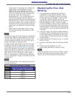
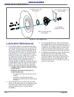
Page 30: ...mponents The rebuild kit comes with instructions PN 219946 Installation of the HSL hub rebuild kit requires a die PN 218733 to set the bearing and seals 2 When lubricating the HSL SAE multi purpose EP...

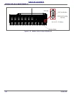
Page 31: ...after have set for a period It is always a good idea to rotate the rubber rollers after making adjustments to assure an adequate clearance between the roller and the scrapers The scrappers will requi...

Page 32: ...4 16 F 894 0919 OPERATION AND MAINTENANCE TABLE OF CONTENTS Figure 4 10 Rubber Roller Scraper Adjustment Scraper 3 8 Flat Washer 3 8 16 Self Locking Hex Nut 3 8 16 X 1 1 4 Screw Rubber Roller...

Page 33: ...after full extension Front wing gauge wheels not level with center section See Synchronizing and Leveling Front Gauge Points on page 4 3 Rear depth gauge reel roller bearing frozen Replace the bearin...

Page 34: ...ic wing down pressure is not operating correctly Make certain that the indicator gauge is showing the recommended pressure and the flow is not excessive Hydraulic wing down pressure is too high and ce...

Page 35: ...l Machine will not unfold raise wing frames out of transport saddles Tractor valve not working Try a different tractor circuit known to work Limit valve on hitch safety circuit not closing b pass circ...

Page 36: ...installed with lips points outward away from the hub Draft comp pressure goes to 3000 psi during maintenance adjustment Draft comp maintenance is hooked up in reverse at the tractor Reverse the couple...

Page 37: ...Document Control Revision Log Date Form New Updated Improvement s Description and Comments 02 2017 F 894 0217 New Initial Release 09 09 2019 F 894 0919 Update Update to new format GG...

Page 38: ...Landoll manufacturing facilities Model 7833 High Speed Landoll HSL Operator s Manual LANDOLL CORPORATION 1900 North Street Marysville Kansas 66508 785 562 5381 800 428 5655 WWW LANDOLL COM Copyright...

Reviews: