OPERATION AND MAINTENANCE
4-13
•
During periods of increasing and or decreasing
temperatures, circuit maintenance maybe
required. The draft compensator circuit will
require maintenance if the pressure is too high or
too low. To maintain the circuit, first adjust the
tractors flow on the circuit being used to
approximately 20%. Then connect the circuit to
the tractor and operate it until the indicated
pressure stabilizes at the desired target setting. If
the pressure rises to 3,000 psi, you are operating
the circuit in reverse and you will need to reverse
the direction of flow and operate the circuit until
the pressure has stabilized at the desired target
setting.
•
Always keep the valve labeled “VALV” turned
OFF when maintaining and operating the draft
comp circuit.
NOTE
The draft comp pressure should always be checked when
the draft comp cylinder is fully extended (mast pin fully
forward). The draft comp pressure will increase as the
large tilt cylinder fully extends, causing the draft comp
cylinder to partially or completely retract.
Typically, the draft compensation circuit will not require
any attention other than a quick glance and note of the
stored pressure once a day.
for those times
your draft compensator circuit needs to be maintained.
These pressures are a good place to start. Never run the
HSL draft compensator at less than 1,100 psi or more
than 2000 psi. You may find that your HSL operates
better at a slightly higher or lower pressure, depending
on your working depth, soil type, soil condition, and other
considerations.
NOTE
The Tilt Controlled HSL is not compatible with the Draft
Compensator System.
Replacing the Disc Hub
Bearing
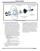
1.
The replacement hub and bearing assembly is
available as a pre-assembled assembly, Landoll
185742 for your convenience. Should you choose,
the wear parts are also available in a kit to re-build
the disc hub. Landoll kit 219945 includes the
essential wear parts to rebuild a disc hub in the field.
When rebuilding disc hubs in the field it is highly
recommended that you obtain a die, Landoll 218733,
to assist in the proper assembly of the components in
the hub assembly. Landoll Corporation will not accept
responsibility for, or warranty hub assemblies re-built
in the field.
2.
Clean the O-Ring groove and the surfaces between
the hub face and the correlating disc surface. Failure
to clean the surfaces mentioned above, can cause
the disc blade to loosen and cause water to infiltrate
the bearing area.
3.
Always replace the 1-8 flanged top lock nut, (Landoll
Part No. 174732.)
4.
Use 242 Loctite (Blue) when assembling the spindle
nut
5.
Always torque the flange top lock nut to
approximately 200-250 foot pounds of torque.
NOTE
Inadequate torquing of the disc hub (<120 ft/lb.) flanged
top lock nut will cause premature bearing failure. Over
torquing can also lead to premature bearing failure.
7833 Draft Hydraulic Settings
Model
MAX* Draft Comp Pressure Setting
(When Cylinder Is Fully Extended)
7833-25
1,100 psi.
7833-30
1,300 psi.
7833-35
1,500 psi.
7833-40
1,700 psi.


