


4-10
F-140-0512 Edition
OPERATION AND MAINTENANCE
Tool Hold Down Springs
The hold down springs are on either side of the parallel
linkage on the tool frames and are factory adjusted for
most normal conditions. Tightening the springs increases
the ground tool pressure. Too much pressure will shorten
the life of the ground tools.
Hydraulic Maintenance
1.
Check the tractor hydraulic fluid level per tractor
owners manual and after any leakage. Check fluid
level with the cylinders in the retracted position.
2.
If a cylinder leaks, disassemble the parts to
determine the cause of the leak. Any time a cylinder
is opened up, or whenever any seal replacement is
necessary, it is advisable to clean all parts and
replace all seals Seal kits are available from your
Landoll dealer.
3.
Check all hydraulic hoses weekly, Look for binding or
cracking. Replace all worn or defective parts
immediately.
Lubrication
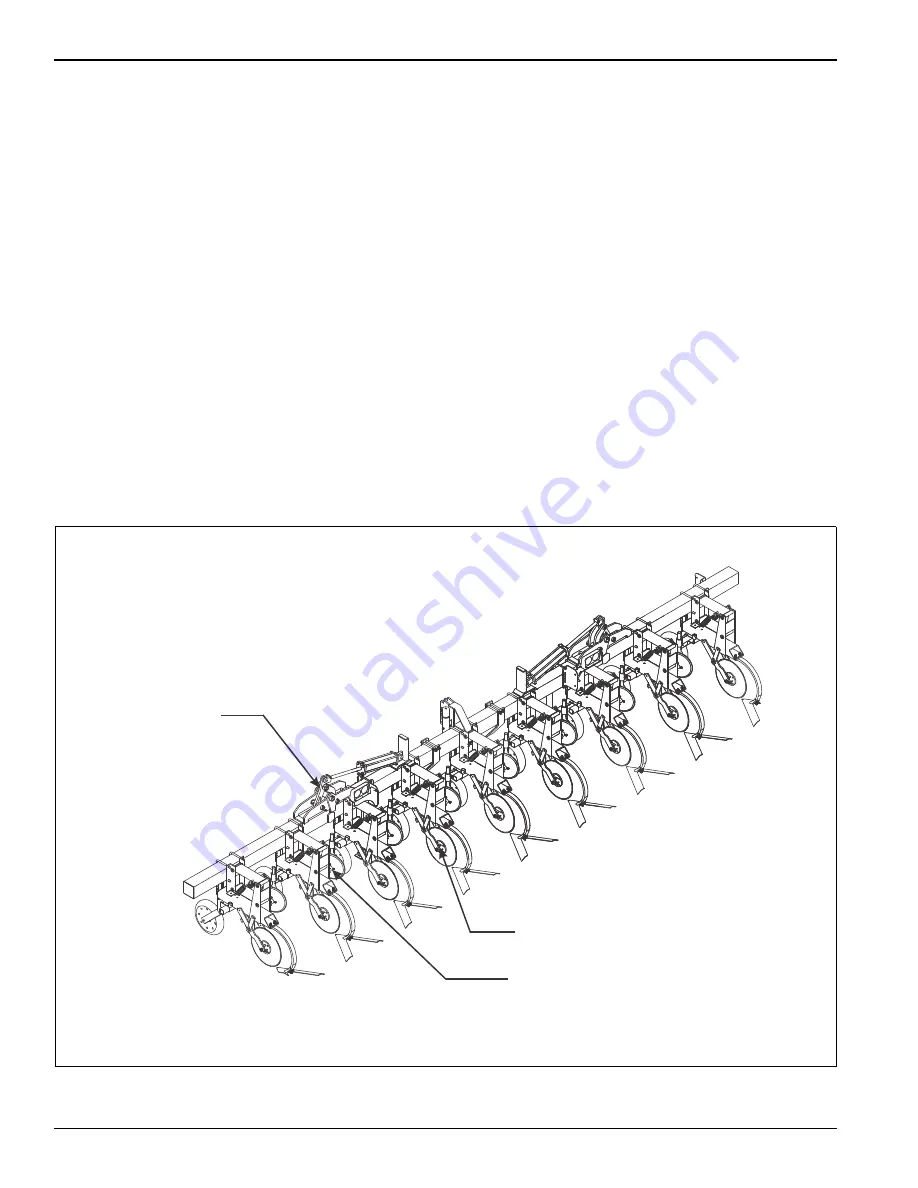
See Figure 4-10
for lubrications points and
recommended maintenance schedule.
1.
The coulter hub bearings, and disc hiller bearings
should be lubricated with a high grade multi-purpose
grease twice a day or every five hours. They should
be filled till the grease is forced past the seals. This
will not damage the seals.
2.
The wing fold pins (if applicable) should be greased
daily with a high grade multi-purpose grease.
Figure 4-10: Lubrication Schedule
HINGE POINTS
(50 HOURS)
COULTER ASSEMBLY
BEARINGS (5 HOURS)
DISC ASSEMBLY
BEARINGS
(5 HOURS)
2000b row crop lube
Summary of Contents for 2000 Series
Page 2: ......
Page 10: ...2 4 F 140 0512 Edition STANDARD SPECIFICATIONS...
Page 25: ...ASSEMBLY INSTRUCTIONS 3 15 Notes...
Page 26: ...3 16 F 140 0512 Edition ASSEMBLY INSTRUCTIONS...
Page 38: ...4 12 F 140 0512 Edition OPERATION AND MAINTENANCE...
Page 40: ...5 2 F 140 0512 Edition TROUBLESHOOTING GUIDE Notes...
Page 41: ......