Landis+Gyr Heat Meter Ultrasonic UH50 Installation And Service Instructions Manual Download Page 1

 
UH50 Ultrasonic Heat Meter 

Subject to change without prior notice 

UH 206-101c 

Page 1 / 8 

Heat Meter Ultrasonic

®

 UH50

Installation 

UH 206-101c

and Service Instructions 


Version: October 2007

Safety information


)

  Do not pick up by the electronic unit 

)

  Be careful of sharp edges (thread, flange, 

measuring tube) 

)

  Installation and removal must be performed 

by qualified personnel only 

)

  Mounting and unmounting are only permitted 

when the system is not under pressure 

)

  After installation, a tightness test must be 

conducted with cold pressure 

)

  Only ever use under service conditions, 

otherwise dangers can arise and the warranty 
may be voided 

)

  Breaking the calibration seal voids the 

warranty 

)

  The 110 

230 

V versions must only be 

connected by an electrician 

)

  The lithium batteries must be properly 

returned 

)

  Lightning protection cannot be ensured; this 

must be provided by the building wiring 

)

  Only one compartment for the power supply 

must be equipped – do not remove the red 
locking hatch 

General information 

The electronic unit is plugged onto an adapter plate 
and can be separated by pushing the volume 
measuring unit upward. 


The packaging should be kept so that the heat 
meter can be shipped in its original packing after the 
calibation period has elapsed. 
If the heat meter was not supplied with a battery 
connected, the current date and time must be 
entered during start-up (see “Parameter setting”). 
The  110 V / 230 V  power  supply  units  comply  with 
safety class II, so the line voltage does not need to 
be disconnected when changing the unit. 
All cables must be laid at a 

minimum distance of 

300 mm

 from power cables or radio-frequency 

cables. 
By overpressure, cavitation must be avoided in the 
entire measuring range, i.e

. at least 1 bar at q

p

 and 

approx. 3 bar at q

s

 (applies to approx. 80°C). 

The heat meter left the factory in perfect safe 
condition. Calibration, maintenance, component 
replacement, and repairs must only be performed by 
trained personnel who are familiar with the hazards 
involved. The manufacturer will provide further 
technical support on request. Heat meter safety 
marks that are relevant for calibration must not be 
damaged or removed! Otherwise the warranty and 
calibration validity of the device will expire. 
 

Installation 

Choose the mounting location (return or flow) in 
accordance with the labeling on the heat meter. 
Study the table for the dimensions and check that 
there is enough clearance. 

No inlet or outlet sections are necessary. However, 
if the heat meter is installed in the shared return of 
two heating systems, e.g. heating and hot water, the 
mounting location must be a sufficient distance from 
the T element that forms the junction (

min. 10 

×

 DN

to allow the different water temperatures to mix well.  
Before the heat meter is installed, the system must 
be rinsed thoroughly. 
As shown in the examples on Page 2, mount the 
volume measuring unit horizontally or vertically 
between two shut-off valves in accordance with the 
arrow for the direction of flow. The sensors must be 
mounted in the same heating circuit as the volume 
measuring unit. For installation as a 

cold meter, 

see 

the following notes. 
The sensor can be mounted in ball valves, in 
pockets or direct immersed. The end of the sensors 
must extend in any case as far as the center of the 
pipe cross-section. Temperature sensors and screw 
joints must be sealed for protection from tampering. 

 
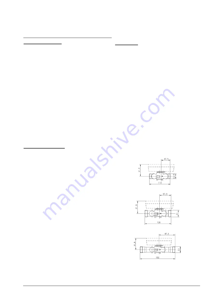
Small heat meters (q

p

 0.6 - 2.5 m³/h) 


Overall length 110 mm (thread) 


Overall length 130 mm (thread) 


Overall length 190 mm (thread) 

3250 006 101 c 

Summary of Contents for Heat Meter Ultrasonic UH50

Page 1: ... cavitation must be avoided in the entire measuring range i e at least 1 bar at qp and approx 3 bar at qs applies to approx 80 C The heat meter left the factory in perfect safe condition Calibration maintenance component replacement and repairs must only be performed by trained personnel who are familiar with the hazards involved The manufacturer will provide further technical support on request H...

Page 2: ...300 56 200 160 18 8 138 24 UH50x 82 60 16 100 360 68 235 180 18 8 158 24 UH50x 83 60 25 100 360 68 235 190 22 8 158 24 Examples of installation Ball valve Example of mounting with a ball valve recommended up to DN25 Welded sleeve with pocket Example of mounting with pockets recommended for DN25 Hint for mounting adapter set sensor direct immersed For heat meters with temperature sensor 5 2x45 mm a...

Page 3: ...n again A heat meter with a removable control cable may be separated during the installation When installation is done be sure that only paired parts volume part calculator are connected together The control cable must not be extended Power supply The heat meter can be powered either with a battery or via power supply modules The 110 V 230 V power supply modules are encapsulated and comply with sa...

Page 4: ...r quantity of heat volume unit status tariff register 1 tariff register 2 isolated bounce free CL module passive 20 mA current loop per EN 62056 21 2002 M bus module per EN 1434 3 fixed and extended variable protocol also for coupling with a suitagle heating controller Analog module Radio module Multi module external These modules are have no effect on consumption metering and can therefore also b...

Page 5: ...sible combinations Factory installed sensors Do not disconnect shorten or extend the cables of factory installed sensors Sensors installed by the customer In the case of sensors provided by the customer max cable length 5 m an extension is impermissible the 2nd and 3rd sleeve from the left must be cut to ensure the correct cable cross sections Unlatch the housing cover by pressing in the side tabs...

Page 6: ...tton 1 applies the value set in the blinking digit The next digit to the right of this then blinks can be set again with the LCD button 2 and can be applied with LCD button 1 As the final acknowledgment of a display line a star symbol is briefly displayed If incorrect entries are made parameter setting be performed again Completing parameter setting Parameter setting mode is exited by pressing LCD...

Page 7: ...ls with date stamp Max heat power on the set day at 2s intervals with date stamp Max temperatures on the set day at 2s intervals with date stamp for flow and return maximum Missing time count on the set day After the last display the previously selected set day is displayed again Pressing LCD button 1 selects the next set day Note If you want to drop out and go directly to the next loop choose a m...

Page 8: ...veraged over a measuring period of for example 60 min The maximum values from the average calculation are preceded by Ma on the LC display The 8 digit property number also the secondary address in M bus operation can be set in parameter setting mode The unit number is assigned by the manufacturer The operating time is counted from the first time the power supply is connected Missing times are summ...

Reviews: