background image

VNG/VLP SERIES PRESSURE WASHER


 OPERATOR’S MANUAL

6

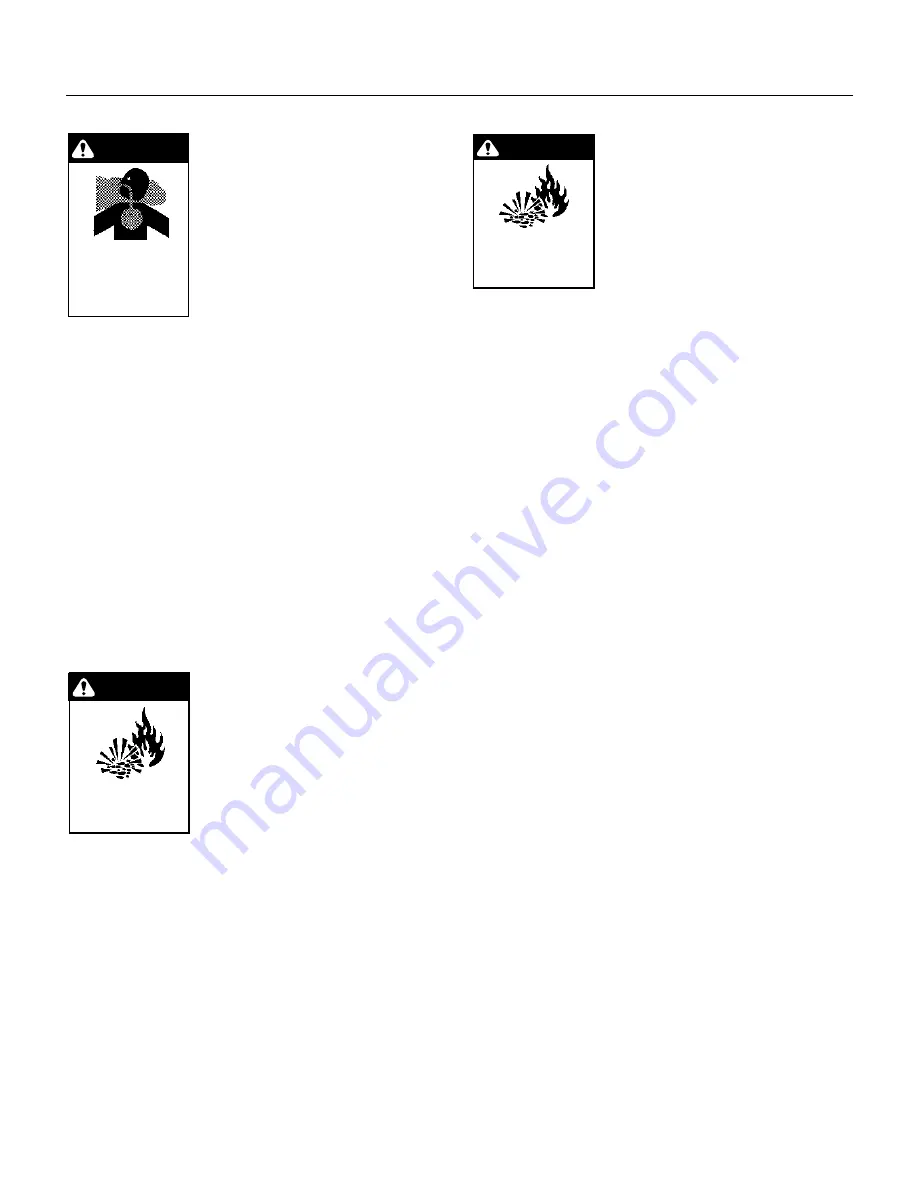
WARNING: Risk of asphyxiation.
Use this product in a well ventilated
area.

  9. When the unit is working, do not

cover or place in a closed space
where ventilation is insufficient.

10. Units with shut-off gun should not

be operated with the trigger in the
off position for extensive periods
of time as this may cause dam-
age to the pump.

11. Protect from freezing.

12. Be certain all quick coupler fittings are secured be-

fore using pressure washer.

13. Do not allow acids, caustic, or abrasive fluids to pass

through the pump.

14. Inlet water must be cold.

15. Do not allow CHILDREN to operate the pressure

washer at any time.

16. The best insurance against an accident is precaution,

and knowledge of the machine.

17. Do not operate this product when fatigued or under

the influence of alcohol or drugs.  Keep operating area
clear of all persons.

18. Do not replace LP Tank while unit is running. Serious

injury could result.

WARNING: Use vapor fuel only.

19. The VLP models are designed to

run on vapor propane fuel. Do not
use liquid fuel. Have a qualified
serviceman install and service
your equipment.

20. Never expose a spark or flame

where there may be unburned
gas present.

21. L.P. gases are heavier than air

and will spill out on the floor. Therefore always provide
adequate space and ventilation around these units.
Install the machine 18” above the floor.

22. Landa will not be liable for any changes made to our

standard units, or any components not purchased from
Landa.

23. Do not overreach or stand on unstable support. Keep

good footing and balance at all times.

24. Follow the maintenance instructions specified in the

manual.

25. When making repairs disconnect from electrical source

and shut off gas valve.

26. Turn burner off and cool to 100° before turning ma-

chine off.

WARNING: If you smell gas, shut off
the gas supply to the appliance

27. Extinguish any open flame, and

test all joints with a soap solution.
If the odor persists, call your gas
supplier immediately.

28. This machine must be attended

during operation.

29. Not suitable for connection to Type B gas vent if the

stack temperature exceeds 243° C (470° F).

30. A draft hood shall be installed if this machine is going

to be permanently installed and vented to the outside
of the building.

INSTALLATION

Place machine in a convenient location providing ample
support, draining and room for maintenance.

Location:

This machine is certified for indoor installation. Its location
should protect the machine from damaging environmen-
tal conditions, such as wind, rain and freezing.

1. The machine should be run on a level surface where

it is not readily influenced by outside sources such as
strong winds, freezing temperatures, rain, etc. The unit
should be located considering accessibility of the com-
ponents and the refilling of detergents, adjustments
and maintenance. Normal precautions should be taken
by the operator of the unit to prevent excess moisture
from reaching the power unit or electrical controls.

2. It is recommended that a partition be made between

the wash area and the machine to prevent direct spray
from the gun from coming in contact with the machine.
Excess moisture reaching the pressure washer or the
electrical controls will reduce the life of the unit and
may cause electrical shorts.

3. During installation of the unit, beware of poorly venti-

lated locations or areas where exhaust fans may cause
an insufficient supply of oxygen. Sufficient combus-
tion can only be obtained when there is a sufficient
supply of oxygen available for the amount of fuel be-
ing burned. If it is necessary to install a unit in a poorly
ventilated area, outside fresh air may have to be piped
to the burner and a fan installed bringing the air into
the area

4. Do not locate near any combustible material. Keep all

flammable material at least 20 feet away.

Allow enough space for servicing the unit.

Local code will require certain distances from floor
and walls. (Two feet away should be adequate.)

A

VOID


SMALL


LOCATIONS


OR


AREAS


NEAR


EXHAUST


FANS

.

WARNING

RISK OF EXPLOSION:

IF GAS SMELL IS

PRESENT, TURN OFF

SUPPLY.

WARNING

RISK OF

ASPHYXIATION. USE

THIS PRODUCT ONLY

IN A WELL

VENTILATED AREA.

WARNING

RISK OF FIRE OR
EXPLOSION, USE

VAPOR FUEL ONLY.

Summary of Contents for VNG/VLP3-11021D

Page 1: ...1B R VNG VLP4 20021C VNG VLP4 30021F VNG VLP8 25021C VNG VLP4 20021C R VNG VLP4 30021F R VNG VLP8 25021C R VNG VLP4 20021F VNG VLP6 30021B VNG VLP8 25021F VNG VLP4 20021F R VNG VLP6 30021B R VNG VLP8...

Page 2: ...d Check Lists 10 11 Operating Instructions 12 Preventative Maintenance 12 General Operating Techniques 12 Component Identification 13 14 Maintenance Service 15 Spray Nozzles 15 Unloader Valves 15 Wint...

Page 3: ...32 Variable Pressure Wand 4 011143A 33 VNG Electrical Box 34 VNG Electrical Box Parts List 35 VNG Remote Electrical Box 36 Troubleshooting 37 41 Burner Specifications 42 Basic Facts 43 Pressure Equiv...

Page 4: ...l installations must comply with local codes Contact your electrician plumber utility company or the selling distributor for specific details WARNING Flammable liquids can create fumes which can ignit...

Page 5: ...must be attended during operation 29 Not suitable for connection to Type B gas vent if the stack temperature exceeds 243 C 470 F 30 A draft hood shall be installed if this machine is going to be perm...

Page 6: ...VNG VLP SERIES PRESSUREWASHEROPERATOR S MANUAL 7 VNG Installation Guide...

Page 7: ...installed must be electrically grounded in accordance with local codes Check for proper power sup ply using a volt meter check the serial plate for the cor rect requirements Gas Piping All piping must...

Page 8: ...standard on all machines When the pressure washer is installed in a tightly closed room without ventilation openings to the outdoors or other rooms provisions shall be made for supplying air for com...

Page 9: ...closed room care should be taken to ensure that an adequate supply of air is available for combustion and ventilation 1 sq inch per 1000 BTU Inspection and Testing Gas Piping The building structure sh...

Page 10: ...i s o l p x e e f i l f o s s o l r o y r u j n i n e h W m e t s y s n o i t i n g i c i n o r t c e l e n a s a h e c n a i l p p a s i h T A y l t c a x e s n o i t c u r t s n i e s e h t w o l l...

Page 11: ...oing to be off for an extended period of time put the manual valve on the gas valve into the OFF position 14 Turn the water off Protect from freezing PREVENTATIVE MAINTENANCE 1 Check to see that the w...

Page 12: ...Light Voltage Light Burner Switch Trigger Draft Diverter High Pressure Nozzle Coupler Water Supply Hose Not Included ChemicalValve Temperature Adjustment Knob Pressure Gauge Pump Switch Coupler Colla...

Page 13: ...Chemical Bucket Not Included Chemical Injector Opt Coupler Collar Discharge Nipple Water Supply Not Included Water Supply Hose Not Included High Pressure Nozzle Coupler Chemical Valve Temperature Adju...

Page 14: ...e unloader may be necessary to maintain correct pres sure See section in manual on unloaders for correct pro cedure in adjusting valve Winterizing Procedure Damage due to freezing is not covered by wa...

Page 15: ...uate floor space and good ven tilation are especially important with propane systems Gas Pressure Requirements All propane fired units operate on vapor propane fuel only They are designed to operate a...

Page 16: ...the water heater will be exposed to freezing weather an anti freeze solution should be circulated through the coil by whatever means are available for the particular system the water heater is used on...

Page 17: ...VNG VLP SERIES PRESSUREWASHER OPERATOR S MANUAL 18 VNG CONTROL PANEL All 20 10 18 9 1 4 6 7 2 3 6 5 8 9 19 22 13 15 27 27 26 26 17 26 16 8 24 23 5 6 21 11 5 14 12 25 26 26...

Page 18: ...00 1 10 1042000 Label 4 2000 1 10 1043000 Label 4 3000 1 10 2063000 Label 6 3000 1 10 2082500 Label 8 2500 1 ITEM PART NO DESCRIPTION QTY 13 95 07163012 Panel Control VNG Large 1 14 6 020251 Switch Cu...

Page 19: ...RESSUREWASHER OPERATOR S MANUAL 20 VNG L EXPLODED VIEW LEFT SIDE 50 49 47 48 44 42 40 19 13 14 22 9 8 7 10 11 31 33 26 36 46 46 45 17 12 3 1 2 4 6 24 23 16 18 36 39 38 37 33 34 15 29 34 25 20 30 27 5...

Page 20: ...MANUAL 21 VNG L EXPLODED VIEW RIGHT SIDE 95 91 71 52 59 96 63 65 66 70 67 79 29 82 94 56 53 93 47 46 51 92 54 101 100 99 35 104 32 32 102 53 103 60 57 58 97 98 55 61 62 107 108 64 77 78 72 75 81 80 83...

Page 21: ...2 27 2 11039 Connector 3 8 Anchor 1 28 2 20070 Nipple 3 8 x 3 8 NPT ST Male 1 29 2 1060 Elbow 1 2 JIC x 3 8 90 2 VNG L EXPLODED VIEW PARTS LIST ITEM PART NO DESCRIPTION QTY 30 90 4001 Washer 5 16 Flat...

Page 22: ...ow 3 4 JIC x 3 4 90 2 85 2 1007 Nipple 1 2 Hex 1 86 2 1033 Tee 3 4 Female Pipe 1 ITEM PART NO DESCRIPTION QTY 87 2 1062 Elbow 1 2 JIC x 1 2 90 1 88 2 0053 Elbow 1 2 JIC 3 8 Steel 90 1 89 5 2309 Pump G...

Page 23: ...VNG VLP SERIES PRESSUREWASHER OPERATOR S MANUAL 24 VNG L BURNER ASSEMBLY 1 2 3 3 2 6 11 13 6 5 19 18 16 1 4 7 8 9 10 7 12 14 15 17 20 6...

Page 24: ...T x 11 Black Pipe Sch 40 1 10 2 0086 Union 1 Black Pipe 1 11 2 00171 Nipple 1 Close Black Pipe 1 12 90 19710 Screw 1 4 x 3 4 HH NC Whiz Loc 4 VNG L BURNER ASSEMBLY PARTS LIST ITEM PART NO DESCRIPTION...

Page 25: ...ERIES PRESSUREWASHER OPERATOR S MANUAL 26 VNG S EXPLODED VIEW LEFT SIDE 2 4 32 29 30 1 7 6 8 5 4 11 23 28 23 19 27 26 15 25 17 31 24 21 20 17 16 41 10 35 37 12 22 33 34 3 5 13 14 18 122 42 38 39 123 3...

Page 26: ...16 53 79 72 79 71 115 75 57 76 45 44 3 62 67 28 68 83 104 105 101 103 101 97 92 88 98 33 95 34 87 85 111 106 108 112 39 84 90 18 96 51 91 93 94 102 100 99 82 61 18 46 78 65 59 50 51 79 56 55 79 80 81...

Page 27: ...MT x Insert 1 4 02120000 Hose 3 4 Push on ft 3 23 2 3014 Valve Fluidmaster 400A Float 3 1100 Qty 1 4 2000 3000 Qty 2 24 2 0114 Tank Plastic Universal Float 1 VNG S EXPLODED VIEW PARTS LIST ITEM PART...

Page 28: ...07163077 Pipe 1 NPT 18 Blk Sch 40 1 75 2 00291 Elbow 1 Blk Pipe 1 76 2 00132 Nipple 1 x 6 Blk Pipe 1 77 95 07121113 Insulation Retainer Plate 1 7 0144 Gasket Retainer Plate 1 ITEM PART NO DESCRIPTION...

Page 29: ...1 5 40208401 Pulley 2 AK 84 H 4 2000 1 5 40508001 Pulley 2 BK 80 H 4 3000 1 110 5 601035 Belt A 35 3 1100 1 5 602036 Belt AX 36 4 2000 2 5 604036 Belt BX 36 4 3000 2 111 5 512024 Bushing H x 24 mm 1...

Page 30: ...Cage 3 8 x 12 ga 2 10 1 96710600 Washer 4 11 1 99364400 Screw 4 12 90 2007 Nut 3 8 Hex NC 2 13 90 4002 Washer 3 8 SAE Flat 2 ITEM PART NO DESCRIPTiON QTY 14 90 1025 Bolt 3 8 x 5 1 2 NC HH Tap 2 15 2 1...

Page 31: ...ucet 1 7 1 90357500 O Ring 1 8 1 10008566 Valve Seat 1 9 1 90357700 O Ring 1 10 1 90503300 Anti extrusion Ring 1 11 1 10007366 Sutter 1 ITEM PART NO DESCRIPTION QTY 12 1 90383500 O Ring 1 13 1 1000796...

Page 32: ...Econo Wand 12 83 004380010 Plastic Handle Right Side 13 83 004170417 3 8 Inlet Tube Heavy Duty Wand SS 14 83 004150404 Adapter Reducer 15 83 004160129 Plastic Handle Left Side 16 83 004130105 Plastic...

Page 33: ...VNG VLP SERIES PRESSUREWASHER OPERATOR S MANUAL 34 VNG ELECTRICAL BOX All Models 18 17 19 13 3 16 4 5 4 2 1 15 6 7 8 12 9 10 11 5 3 14...

Page 34: ...5 Overload GE RTAIP 4 3C 1 6 1254 Overload BD FGZIN 4 3F 1 6 1263 Overload GE RTA2F 6 3B 1 8 25B 6 1258 Overload GE RTAIT 6 3C 1 8 25C 8 3F ITEM PART NO DESCRIPTION QTY 6 95 07163028 Box Elec VNG L 1...

Page 35: ...NG VLP SERIES PRESSUREWASHER OPERATOR S MANUAL 36 VNG REMOTE ELECTRICAL BOX All Models N 3 7 16 17 21 23 24 28 6 0517 6 05041 10 3014 6 02053 6 021630 10 02021 6 021626 6 0390 6 021623 6 021626 6 0390...

Page 36: ...n gas valve gas cock or selector arm is turned on 2 With gas on and system sparking probe terminals PV and TR If pilot gas does not flow with 24 volts at these terminals replace gas valve 3 If you do...

Page 37: ...h t n o e m a l f n o i t i n g i e h t e c a l p e r t o n s e o d t i f I n o n r u t d l u o h s t i n u l o r t n o c F O G N I L C Y C T R O H S N I A M R E N R U B N I A M S N R U T R E N R U B...

Page 38: ...n i n a e l C s e v l a v e g r a h c s i d r o t e l n i n r o W t i k e v l a v h t i w e c a l p e R e l z z o n y a r p s n i n o i t c u r t s b O n o i t c u r t s b o e v o m e R e v l a v l o...

Page 39: ...u l p e s o h n o i t c u s e c a l p e r r o n a e l C g n i g g u l p l a c i m e h c p u d e i r D e v l a v g n i r e t e m y l h g u o r o h t n a e l c d n a e l b m e s s a s i D l a c i m e h...

Page 40: ...harge valve springs Check and replace if necessary Excessive matter in valves Check and clean if necessary Worn bearings Check and replace if necessary PRESENCE OF WATER IN OIL Oil seal worn Check and...

Page 41: ...0 7 4 3 o N 0 0 0 3 4 G N V 4 4 X 4 5 C H R V M 0 0 0 7 4 3 o N 0 0 0 3 6 G N V 8 9 X 4 5 C H R V M 0 0 0 7 1 o N 0 0 5 2 8 G N V 8 9 X 4 5 C H R V M 0 0 0 7 1 o N 0 0 0 1 3 P L V 4 4 X 9 6 t i K C H...

Page 42: ...t Therm Therm hour 50 Therm Example Using natural gas 400 000 BTU Machine 400 cubic feet 4 Therms hour 4 x 50 2 00 hour to run Simply stated pressure is the force exerted by a gas or liquid attempted...

Page 43: ...nce Last Oil Change E L U D E H C S E C N A N E T N I A M l i O p m u P t c e p s n I y l i a d l e v e l l i O e g n a h C y l l a u n n a r o s r u o h 0 0 5 y r e v e n e h t s r u o h 0 5 t s r i...

Page 44: ...ioration scale build up rust corrosion or thermal expansion 4 Damage to components from fluctuations in electrical or water supply 5 Normal maintenance service including adjustments fuel system cleani...

Page 45: ...4275 N W Pacific Rim Blvd Camas WA 98607 Form 96 610 Revised 5 99 Printed in U S A for Landa Inc Camas WA 98607 WATER CLEANING SYSTEMS...

Reviews: