Section 1: Assembly & Set-Up
RCFM4014 Rotary Cutter 326-730M
12/11/18
19
3. Start tractor, raise implement fully up. Back
implement over the support blocks. Do not lower
implement onto the support blocks.
4. Without changing the 3-point lift height, shut tractor
down using
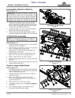
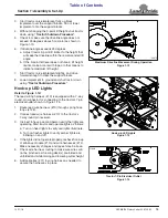
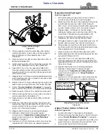
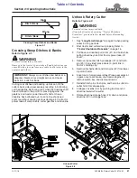
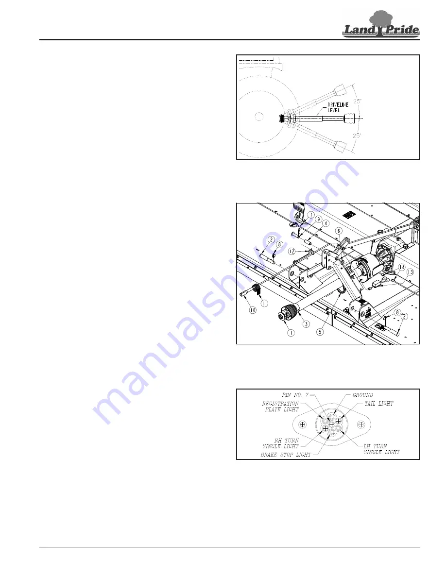
5. Check to make sure the driveline angle does not
exceed 25 degrees above horizontal as shown in
Figure 1-13.
6. If driveline angle exceeds 25 degrees:
a. Adjust tractor 3-point lift limiter to the height that
will keep the driveline within the recommended lift
angle.
b. If the 3-point left lever does not have a lift height
limiter, make a mark with tape or other means to
indicate maximum lift height.
7.
Start tractor, raise implement slightly, and drive
forward enough to clear the support blocks.
8. Lower implement to ground and shut tractor down
using
Hook-up LED Lights
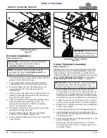
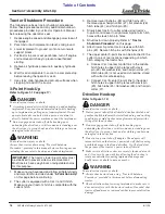
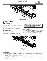
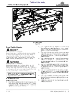
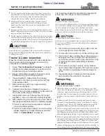
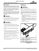
The lead wiring harness (#10) is equipped with a 7-way
round pin connector for connecting to the tractor’s 7-pin
electrical outlet shown in Figure 1-15.
1.
Route lead wire harness (#10) through spring hose
loops (#128).
2. Connect lead wire harness (#10) to the tractor’s
7-way round pin receiver.
3. It is best to have a second person verify the lights are
operating. Start tractor and operate lights as follows:
a. Turn on head lights to verify red lights illuminate.
b. Turn on flasher lights to verify amber lights are
blinking on and off.
4. If the lights did not operate properly, recheck hook-up
of enhance module (#13) and wire harnesses (#14).
Make necessary changes and repeat step 3 above.
5. Check wire harness routing to make sure wires will
not be pinched as the wing deck(s) are folded and
unfolded and while raising and lowering cutter height.
6. Add cable ties (#11) to wire harness as needed to
secure the harnesses in place.
Maximum Driveline Movement During Operation
Figure 1-13
Hook-up LED Lights
Figure 1-14
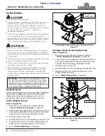
Tractor 7-Pin Electrical Outlet
Figure 1-15
24872
11640


