Section 5: Maintenance & Lubrication
RC3614 & RCM3614 Rotary Cutters 330-918M
1/20/21
46
Clutch Disassembly, Inspection & Assembly
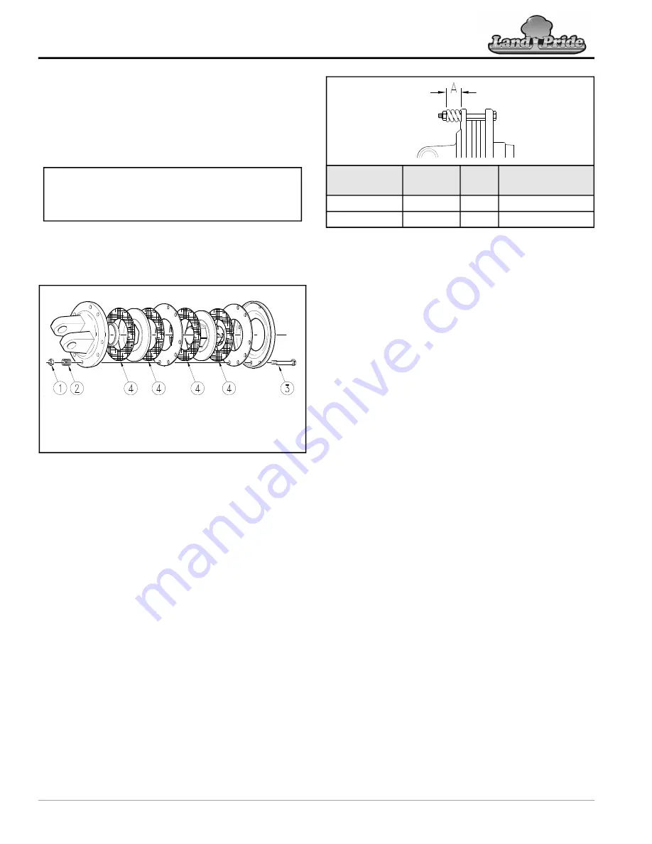
Refer to Figure 5-9:
If clutch run-in procedure above indicated that one or more
friction disks did not slip, then the clutch must be
disassembled to separate the friction disks.
Disassembly
1. Removing spring retainer nuts (#1), springs (#2), and
bolts (#3).
2. Separate disk (#4) from metal surfaces adjacent to
them.
Type A Clutch Assembly
Figure 5-9
Inspection
Inspect all parts for excessive wear and condition. Clean
all parts that do not require replacement.The original
friction disk thickness is 1/8" (3.2mm) and should be
replaced if thickness falls below 3/64" (1.1mm). If
clutches have been slipped to the point of “smoking”, the
friction disks may be damaged and should be replaced.
Heat build-up may also affect the yoke joints.
Assembly
1. Reassemble each friction disk (#4) next to the metal
plate it was separated from.
2. Install bolts (#3) through end plates and intermediate
plates as shown.
3. Place springs (#2) over the bolts and secure with
nuts (#1).
Refer to Figure 5-10:
4. Progressively tighten each spring retainer bolt until
correct spring height “A” is reached.
IMPORTANT:
Not all clutches are assembled the
same with the same number of components. Be sure
to keep track of order and orientation of your clutch
components during disassembly.
14714
IMPORTANT: Keep
track of order and orientation of
your clutch components during disassembly
Type A Clutch Adjustment
Figure 5-10
24600
Driveline No.
Driveline
Location
Cat
No.
A (inches)
Spring Height
826-494C
Wing
5
1.32 in. / 33.5 mm
826-495C
Center
5
1.32 in. / 33.5 mm


