background image

32

Section 4 Maintenance and Lubrication

Z52®, Z60® & Z72® Zero Turning Radius Mowers Accu-Z   356-005M

03/11/03

Land Pride

Maintenance

!

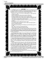
WARNING!

Unless specifically required, DO NOT have engine running
when servicing or making adjustments to mower. Place control
levers in the neutral position, disengage deck clutch, and
remove ignition switch key. Repairs or maintenance requiring
engine power should be performed by trained personnel only.
To prevent carbon monoxide poisoning, be sure proper
ventilation is available when engine must be operated in an
enclosed area. Read and observe safety warnings in front of
manual.

!

DANGER!

Before working on or under the deck, make certain engine
cannot be accidentally started. Shut engine off and remove
ignition switch key for maximum safety. Repairs or maintenance
requiring engine power should be performed by trained
personnel only.

!

DANGER!

Exercise caution when working under the deck as the mower
blades are extremely sharp. Wearing gloves is advisable when
working around or with the blades.

!

WARNING!

Except when changing or checking belt, always keep belt covers
on mower for safety as well as cleanliness.

!

WARNING!

When possible, clean under mower using a stick or similar
instrument making sure that no part of the body, especially arms
and hands are under mower.

Regular maintenance is the best prevention for costly
downtime or expensive, premature repair. The following
pages contain suggested maintenance information and
schedules which the operator should follow on a routine
basis.

Remain alert for unusual noises, they could be signaling a
problem. Visually inspect the machine for any abnormal
wear or damage. A good time to detect potential problems
is while performing scheduled maintenance service.
Correcting the problem as quickly as possible is the best
insurance.

!

WARNING!

Keep your machine clean and remove any deposits of trash and
clippings, which can cause engine fires and hydraulic
overheating as well as excessive belt wear.

Clear away heavy build-up of grease, oil and dirt,
especially in the engine and hydraulic reservoir area;
minute dust particles are abrasive to close-tolerance
engine and hydraulic assemblies.

Daily inspect mower for grass clippings and wire and
string tangles. The underside of the mower deck will
collect a build-up of grass clippings and dirt, especially
when grass is wet or has high moisture content. This
build-up will harden, restricting blade and air movement
and will probably show a poorer quality of cutting.
Therefore it should be removed routinely.

To do this it will be necessary to raise and block the deck
in the full up position and scrape the build-up from
underneath.

Some repairs require the assistance of a trained service
mechanic and should not be attempted by unskilled
personnel. Consult your Land Pride dealer when
assistance is needed.

Torque Values

!

WARNING!

Particular attention must be given to tightening the drive wheel
lug nuts, wheel motor nuts, and blade spindle nuts. Failure to
correctly torque these items may result in the loss of a wheel or
blade, which can cause serious damage or personal injury.

It is recommended that these be checked after the first 2
hours of initial operation and every 50 hours following
removal for repair or replacement.

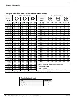
For all other torques refer to “Torque Values Chart”
page 44.

For engine torque values, see engine owner’s manual.

Tires

It is important for level mowing that the tires have the
same amount of air pressure.

Refer to “Tire Inflation Chart” page 44.

Solid fill tires are not recommended for the Accu Z mower.
On any machine, with solid filled tires, the warranty claim
will be denied.

NOTE: After completing maintenance cycle
(500 hours), repeat cycle.

Torque Values

FT - lbs.

Nm

Wheel lug nuts

65 - 75

88.14 - 101.7

Wheel motor nut

350 - 375

474.6 - 508.5

Blade spindle bolts (top
and bottom)

65 - 75

88.14 - 101.7

Summary of Contents for Accuz Z52

Page 1: ...03 Printed Read the Operator s manual entirely When you see this symbol the subsequent instructions and warnings are serious follow without exception Your life and the lives of others depend on it 356...

Page 2: ...on 13 Controls 13 Ignition Switch 13 Throttle Control 13 Choke Control 13 Control Levers 13 Parking Brake 14 Deck Clutch Switch 14 Deck Lift Pedal 14 Instrumentation 15 Electronic Hour Meter 15 Oil Pr...

Page 3: ...ponents that for functional purposes cannot be guarded Indicates a potentially hazardous situation which if not avoided could result in death or serious injury and includes hazards that are exposed wh...

Page 4: ...eration Safety at All Times Thoroughly read and understand the instructions given in this manual before operation Refer to the Safety Label section read all instructions noted on them Operator should...

Page 5: ...ive gloves and safety glasses or goggles when working with hydraulic systems If an accident occurs see a doctor immediately Any fluid injected into the skin must be surgically removed within a few hou...

Page 6: ...u Z 356 005M 03 11 03 Land Pride 838 303C Danger Battery Beneath Seat 19097 838 305C Warning Rollover Hazard Beneath Bumper on Back of Frame 19098 19097 838 306C Warning Do not operate without deflect...

Page 7: ...60 Z72 Zero Turning Radius Mowers Accu Z 356 005M Land Pride 838 310C Warning General 19097 838 308C Warning Rotating Blade Hazard Both Sides 19057 838 399C Warning Fuel Imbedded in Fuel Tank 19057 83...

Page 8: ...from Land Pride are compact in size and ideal for homeowner and commercial grass maintenance The Accu Z is a true zero turn mower When mowing alongside a building or landscaping the Accu Z turns withi...

Page 9: ...es line up and replace the bolts and flat washers Remote Air Cleaner Assembly Refer to Figure 1 2 1 Slide air cleaner clamp 1 over air cleaner housing 2 position the clamp so the bolt holes are facing...

Page 10: ...16 flat washers and two 5 16 nuts 8 Secure hose to the carburetor intake with hose clamp Optional Equipment Assemblies Remote Air Cleaner Assembly Refer to Figure 1 2 page 7 The remote air cleaner is...

Page 11: ...n place Mower Deck Preparation Refer to Figure 1 6 Park the Accu Z mower on a flat surface Shut off the ignition switch and remove the key from the switch Disconnect the negative battery cable Before...

Page 12: ...ley and Pulley Cover Assembly Refer to Figure 1 7 1 Install double pulley 13 with the bolt 11 and existing flat washer 12 Torque bolt 65 75 lbs 2 Reinstall blade drive belt on lower grove of pulley 13...

Page 13: ...tor to existing exhaust and fasten with screw 6 through hole in deflector and drilled hole NOTE Accu Vac Collection System cannot be mounted on Accu Z mowers manufactured with Honda engines Use only w...

Page 14: ...ier Bagger Assembly Figure 1 9 19911 Front Lift and Weight Assembly For Blade Service or Replacement 1 The front weight bracket 1 will mount to the front of the mower frame with the four u bolts 2 loc...

Page 15: ...rd to decrease engine rpm Choke Control Refer to Figure 2 2 A cable is linked to manually operate the engine choke When the lever is in the down position the choke is in the off run position When the...

Page 16: ...igure 2 4 Refer to Figure 2 5 These levers control the mower s speed direction neutral lock and park brake Levers are used to steer accelerate brake and change direction The mower will not move when t...

Page 17: ...the seat The engine should stop within two seconds 6 If the engine fails to stop when the deck clutch switch is up or one or both of the control levers is in and the operator is off the seat check the...

Page 18: ...necessary to move the mower when the engine is inoperative the hydraulic pumps are equipped with bypass valves Before moving the unit turn bypass valves counter clockwise one half to one revolution T...

Page 19: ...etely and thoroughly and should have attempted slow moving maneuvers to become familiar with the operation of the equipment before attempting normal speed operation An inexperienced operator should no...

Page 20: ...ING Never direct discharge of material from mower deck towards bystanders WARNING Never operate the mower deck with discharge chute removed or in raised position WARNING Always check area to be mowed...

Page 21: ...Now slowly pull the levers back toward your body past neutral position The mower will reverse direction and increase in speed as you pull further back If you push one lever forward and pull one lever...

Page 22: ...ting as well as excessive belt wear Clear away heavy build up of grease oil and dirt especially in the area of reservoir and oil and engine combustion air minute dust particles are abrasive to close t...

Page 23: ...in the neutral position Disengage the deck clutch 3 Start the engine and observe which way the wheels are rotating 4 If wheel s are rotating forward loosen the jam nuts on the pump linkage rods and ro...

Page 24: ...wer and loosen the lock nut on the side which is rotating too fast and turn the stop set screw inward to stop the control lever sooner Tighten the lock nut on the stop and test again Repeat this proce...

Page 25: ...cap screws that attach the upper control lever to the lower lever Fig 5 6 the upper control lever can be pivoted to fit the operator s personal preference The control levers should be adjusted so that...

Page 26: ...n with the bypass valves open There should be no resistance from the brakes at this point 5 Move the control lever to where it is touching the outside edge of the lever s travel slot Refer to Figure 3...

Page 27: ...dle belt tension remains constant by means of a tension idler and spring The spring tension should be such that the belt does not slip under normal operating load conditions assuming the belt is not e...

Page 28: ...lacing the height adjusting stop in the 3 hole and turning the height stop so that the flat side is against the stop handle Refer to Figure Figure 3 15 5 Clamp the height adjusting stop against the st...

Page 29: ...of the mower 9 Set the amount of threads protruding on the deck lift rod from the lift block at approximately 1 Refer to Figure 3 20 Nut Nut Chain Deck Lift threaded Rod Deck Level Adjustment Figure...

Page 30: ...the threaded rod until there is slack in the deck lift chain See Figure 3 16 25 Tighten the appropriate nut until the chain just becomes tight 26 Tighten the other nut on the opposite side of the bloc...

Page 31: ...ion can be adjusted up or down as needed from 3 4 to 1 3 4 below the blade surface Move the front wheels up or down in 1 2 increments using the different axle mount holes in the roller mount bracket S...

Page 32: ...uel Tanks 7 Hydraulic Oil Reservoir 8 Deck Idler Zerk 1 9 Deck Pusher Arm Zerks 2 10 Hydraulic Oil Filter 11 Gauge Wheel Bearing Zerks 2 12 Engine Oil Filter 13 Deck Height Pivot Zerks 4 14 Safety Int...

Page 33: ...acks or leaks Maintenance Schedule Service at Intervals Indicated Weekly or 50 Hours Monthly or 100 Hours Annually or 500 Hours Verify Safety Start Interlock System Daily Visually Inspect Unit for loo...

Page 34: ...eep your machine clean and remove any deposits of trash and clippings which can cause engine fires and hydraulic overheating as well as excessive belt wear Clear away heavy build up of grease oil and...

Page 35: ...ttery size is a garden mower BCI group U1R with 225 or better cranking AMP rating A maintenance free battery is recommended Otherwise follow battery manufacturer s maintenance safety storing and charg...

Page 36: ...your hands Relieve all pressure in the system before disconnecting or working on hydraulic lines To relieve pressure place control levers in park The 1 0 U S gallon 3 79 liter hydraulic reservoir is l...

Page 37: ...pen flame or spark if there is fuel in the tank Read and observe safety precautions at front of this manual The fuel tanks are located in the mower s fenders See Figure 4 6 Total capacity for the fuel...

Page 38: ...using dirt ingestion and engine failure It is important to note that whenever an air filter element is cleaned by any method the person or company performing the cleaning assumes responsibility for th...

Page 39: ...hould be reminded that failure to use original equipment replacement parts is an alteration and will not be considered for warranty in the event of engine damage Engine Air Filter Service Procedure 1...

Page 40: ...er attempt to straighten a bent blade by heating or weld a cracked or broken blade as the blade may break and cause serious injury DANGER Never work with blades while engine is running or deck clutch...

Page 41: ...oil of proper viscosity 4 Drain fuel tank and run the engine until it stops from lack of fuel Gasoline evaporates if left in carburetor for long periods forming gum and varnish deposits in carburetor...

Page 42: ...12 volt 20 amp Governor Mechanical Cooling Kawasaki Air cooled Fly wheel fan Honda Air cooled Fly wheel fan with oil cooler Fuel Unleaded gasoline with octane rating of 87 or higher Fuel capacities 1...

Page 43: ...ers molded into the left side fuel tank Accommodates nearly any cup size Hand Operated Controls Choke throttle ignition switch electric mower clutch and Integrated parking brakes Indicators Hour meter...

Page 44: ...r with a high lift design to stand the grass up before cutting Mulching kit A mulching kit is available to recycle clippings and discharge them down into the grass 1 Blade spindles 1 Blades spindles w...

Page 45: ...r check hydraulic pump Poor compression See your dealer Steering linkage needs adjustment Adjust linkage Air in system Check filter fittings For additional causes See engine manual Overheating Air int...

Page 46: ...10 375 M18 X 1 5 220 165 350 260 485 355 3 4 16 260 190 405 295 570 420 M20 X 2 5 280 205 440 325 610 450 7 8 9 225 165 585 430 820 605 M20 X 1 5 310 230 650 480 900 665 7 8 14 250 185 640 475 905 670...

Page 47: ...s the right to inspect any equipment or parts which are claimed to have been defective in material or workmanship This Warranty does not apply to any part or product which in Land Pride s judgment sha...

Page 48: ...Corporate Office P O Box 5060 Salina Kansas 67402 5060 USA www landpride com...

Reviews: